


E
D
C
B
4
5
A
3
CPG #2561255 FIRELARM 2500 Operating Manual
3-7
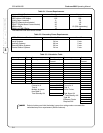
3.8 Notification Appliance Circuits Connections
The control panel has two Style Y (Class B) notification appliance circuits which can be upgraded to Style
Z (class A) by the addition of a model CAM (Class A Module). One module is required for each circuit that
is to be upgraded. See Appendix A for more information.
The notification appliance circuits are power limited, regulated 24 VDC rated at 2.0 amperes max each.
(Total system current not to exceed 2.5 A.)
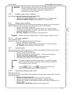
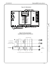
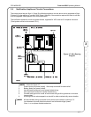
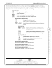
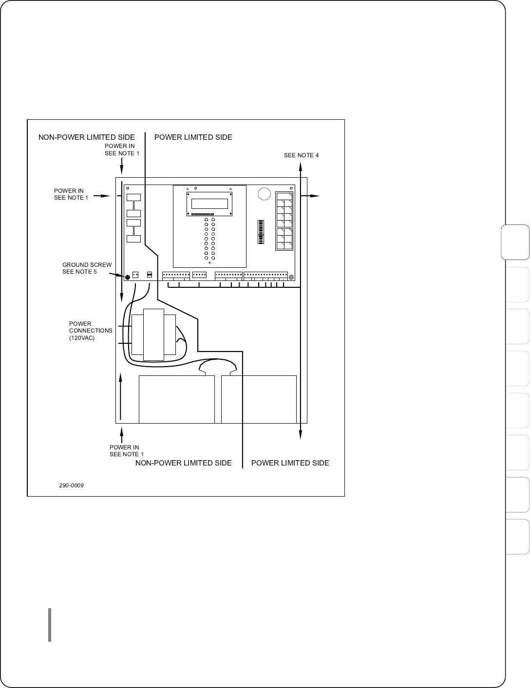
Notes for Figure 3-7:
1. Power inputs (not power limited). Wire wrap to standoff for strain relief.
2. Battery leads (not power limited).
3. Use left hand knockouts for non-power limited wiring.
4. Use right hand knockouts for power limited wiring.
5. Connect earth ground to corner of main board using a #6 ring terminal or wire and
ring provided.
6. All wiring must be wire-wrapped to a standoff or other mechanically secure location.
All field-installed wiring connected to this panel must maintain a spacing of ¼
inch between all power-limited conductors and all electrical light, power,
Class 1, or non-power limited conductors.
Figure 3-7. Wire Routing
Diagram