


OPTIONAL KITS
For special installation applications and modifications, the following kits areavailable from your local dealer. To
ensure safe, efficient operation ofyour Direct VentGas Baseboard be sure to use only authorized kits.
Table 1: S )ecial adaptation and modification kits available for use with the Direct Vent Baseboard Heaters.
MODEL # DES(.RIPTION CONTENTS
VWSK5/10 Vent Weather Seal Kit 2" diameter PVC pipe, external wall seat, O-ring, 2 PVC straps,
PVC glue, instructions.
VRK5/10 Vent Riser Kit Wall mount plate, 21-1/2" stainless steel vent riser, instructions
SVCKS/10 Side Valve Concealer Kit 4" cabinet extension, wall plate, screws, instructions
BVCKS/10 Bottom _atve Concealer Kit 4" cover, wall plate, screws, instructions
WARNING:
STEP 1.
a)
b)
c)
d)
e)
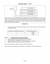
INSTALLATION
Failure to follow these instructions carefully could result in poor performance, property_ dmnage,
personal injury, or loss of life.
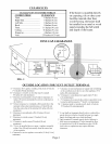
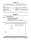
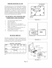
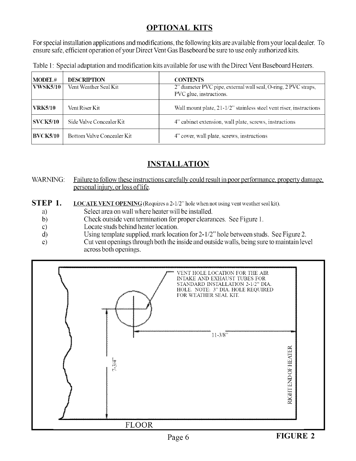
LOCATE VENT OPENING (Requires a 2-1/2" hole when not using vent weather seal kit).
Select area on wall where heater will be installed.
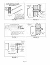
Check outside vent termination forproper clearances. See Figure 1.
Locate studs behind heater location.
Using template supplied, mark location for 2-1/2" hole between studs. See Figure 2.
Cut vent openings through both the inside and outside walls, being sure to maintain level
across both openings.
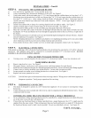
VENT HOLE LOCATION FOR THE AIR
INTAKE AND EXHAUST TUBES FOR
STANDARD INSTALLATION 2-I 2" DIA.
HOLE. NOTE: 3" DIA. HOLE REQUIRED
FOR WEATHER SEAL KIT.
11-3/8"
FLOOR
Page 6 FIGURE 2