


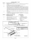
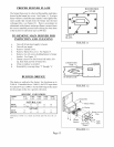
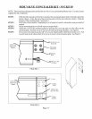
PROPER BURNER FLAME
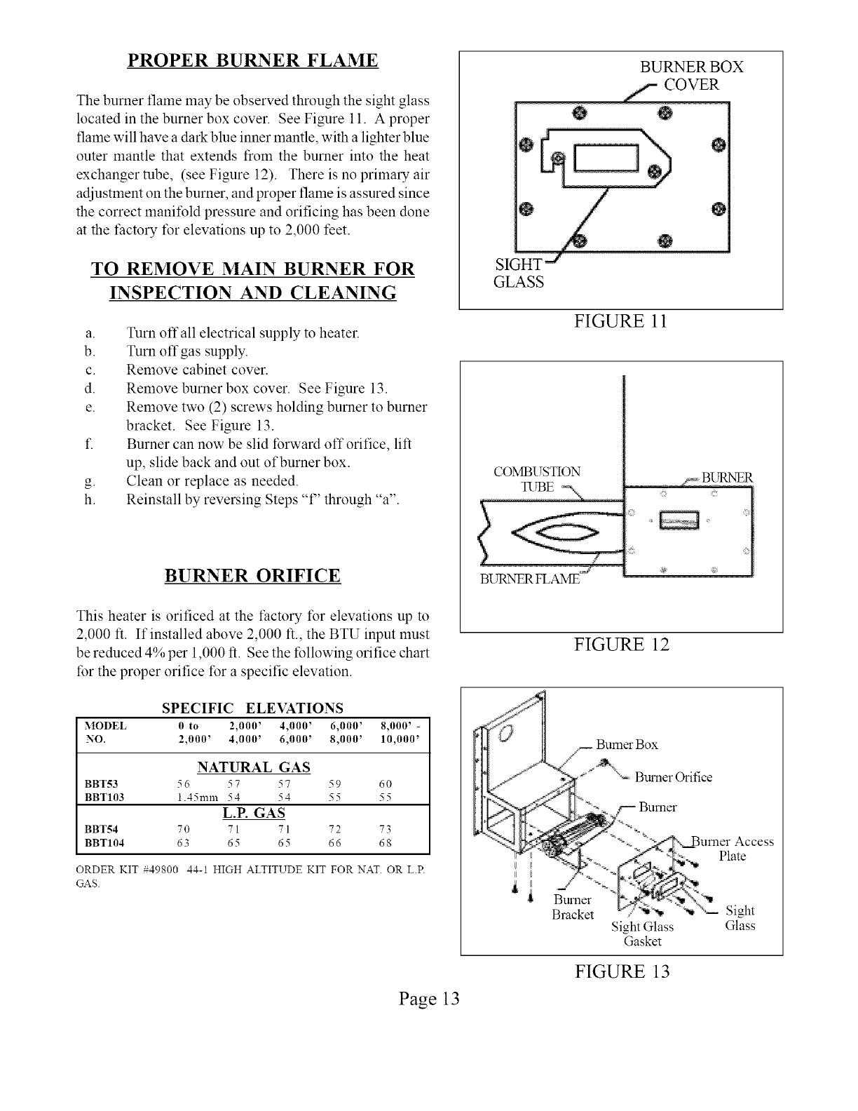
The burner flame may be observed through the sight glass
located in the burner box cover. See Figure 11. A proper
flame will have a dark blue inner mantle, with a lighter blue
outer mantle that extends from the burner into the heat
exchanger tube, (see Figure 12). There is no primary air
adjustment on the burner, and proper flame is assured since
the correct manifold pressure and orificing has been done
at the factory for elevations up to 2,000 feet.
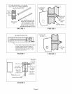
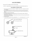
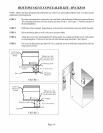
TO REMOVE MAIN BURNER FOR
INSPECTION AND CLEANING
a.
b.
C.
d.
e.
g.
h.
Turn off all electrical supply to heater.
Turn off gas supply.
Remove cabinet cover.
Remove burner box cover. See Figure 13.
Remove two (2) screws holding burner to burner
bracket. See Figure 13.
Burner can now be slid tbrward off orifice, lift
up, slide back and out of burner box.
Clean or replace as needed.
Reinstall by reversing Steps 'T' through "a".
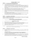
BURNER ORIFICE
This heater is orificed at the factory for elevations up to
2,000 ft. If installed above 2,000 ft., the BTU input must
be reduced 4% per 1,000 ft. See the following orifice chart
for the proper orifice for a specific elevation.
SPECIFIC ELEVATIONS
MODEL 0 to 2,000' 4,000' 6,000' 8,000' -
NO. 2,000' 4,000' 6,000' 8,000' 10,000'
NATURAL GAS
BBT53 56 57 57 59 60
BBT103 1.45mm 54 54 55 55
L.P. GAS
BBT54 70 71 71 72 73
BBT104 63 65 65 66 68
ORDER KIT #49800 44-1 HIGH ALTITUDE KIT FOR NAT. OR L.P.
GAS.
Page 13
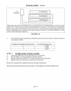
BURNER BOX
O O
• O
@ / @
SIiu_,_.l_ ..................................................O .......................................
GLASS
FIGURE 11
COMBUSTION
BURNER FLAME
FIGURE 12
.... Burner C_ifice
Bumer
Bracket
Sight Glass
Gasket
Burner Access
Plate
Sight
Glass
FIGURE 13