


WIRING
If any of the original wire supplied with heater has to be replaced, it must be replaced with type 105 Degree C wire
or its equivalent.
CAUTION: Label all wires prior to disconnection when servicing controls. Wiring errors can cause improper and
dangerous operation.
Verity proper operation after servicing.
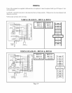
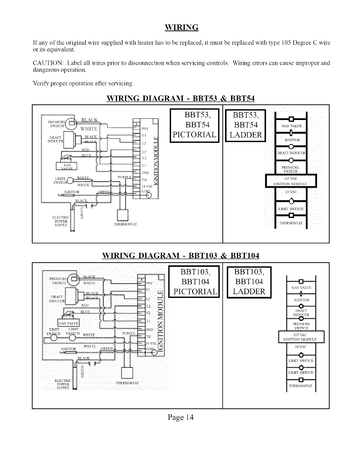
WIRING DIAGRAM - BBT53 & BBT54
PSV
\,q
IL2
v2 N
i1 Z
,NI, _
LIMIT ! PUR _ _ TH
SWITC
24 VA(
IGNITOR _ _ _ _ _
BLACK ,_ i %_
cJ
ELECTRIC ©
POWER
SUPPLY THERMOSTAT
BBT53,
BBT54
PICTORIAL
BBT53,
BBT54
LADDER
IGNITOR
DRAFT INDUCER
PRESSL.qZE
SWITCH
i I
IGNITION MODULE
24 VAC
LIMIT SWITCH
THERMOSTAT
i
WIRING DIAGRAM - BBT103 & BBT104
BBT103,
BBT 104
PICTORIAL
BBT103,
BBT 104
LADDER
POWER THERMOSTAT
SUPPLY
GAS VALVE
IGNITOR
DRAFT
PRESSURE
SWITCH
l 115 _-C
IGNITION MODULE
24 \_C
LIMIT SWITCH
LIMIT SWITCH
THERMOSTAT
1
Page 14