


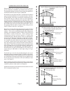
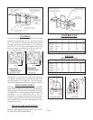
INSTALLATION / WHEN RECESSED
(UP TO 9-1/4”)
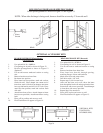
STEP 1.Cut out floor plate between 2x4 studs, so heater
will set flat on floor.
STEP 2.Make electrical connection of 115 V. wiring into
junction box provided on top of header plate.
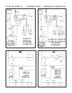
STEP 3.Attach the base plate (purchased with the vent pipe)
to the header plate using two No. 8 sheet-metal
screws through the pre-punched holes. See Figure
B.
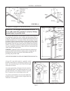
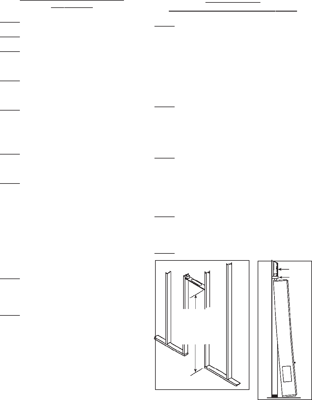
STEP 4.Square up and nail header plate in place between
2x4 studs placed on 16” centers (14-3/8” between
studs). For distances from top of header plate to
floor, see Figure 6.
STEP 5.Remove double ceiling plate between studs. Install
one ceiling plate spacer across the cut out in ceiling
plate. Install vent pipe into position, be sure to
lock bottom of vent pipe into the base plate. Nail
second ceiling plate spacer in place. See Figure
B.
STEP 6.If the vent continues through additional stories
within the 2x4-stud space, then fire stop spacers
must be installed at the second and subsequent
ceiling levels. See Figure C.
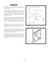
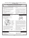
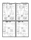
STEP 7.To place furnace into position, grasp furnace and
lift so furnace flue vent and header plate vent
opening engage. Plug power cord from top of
heater into receptacle on bottom of the header plate,
see Figure 3. Run thermostat wire through a drilled
hole into an adjacent stud space. Do not route it
behind the header plate. To do so may cause the
thermostat wiring to chaff resulting in the
appliance operating continually. Connect
thermostat wire with thermostat wires extending
from top of heater. Lift furnace upward and swing
bottom into wall, see Figure 7. Secure furnace in
place using 2 holes provided in bottom of casing.
STEP 8.Make gas connection using connector the same size
as gas connection of furnace. CHECK ALL
CONNECTIONS FOR GAS LEAKS WITH
LEAK DETECTOR SOLUTION. DO NOT USE
OPEN FLAME.
STEP 9.Replace and fasten front panels to furnace.
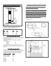
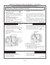
INSTALLATION
WHEN INSTALLED FLUSH TO WALL
STEP 1.After locating furnace, cut 3-1/2”x12” rectangular hole
in ceiling between ceiling joists. Make sure gasket is in
position on the top of the furnace casing around the
flue vent opening. Remove vent collar from top of header
plate and place over flue extension and fasten to
matching holes in casing top, using screws from header
plate. Install B vent type base plate (not supplied) to
top of vent collar. Install ceiling plate spacer to back
wall, centered between studs. Install B type vent to top
of furnace, terminating at least 12’ above the floor and
at least 2’ above the roof line.
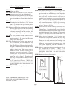
STEP 2.Fasten furnace to wall. To secure top of furnace to wall,
loosen top screws on back casing and raise tabs up.
Tighten screws. Screw through hole in top of tabs into
anchors (not provided). Secure bottom using two holes
provided in bottom of casing. (Optional) Cover exposed
vent with a vent enclosure kit, Part Number 16VE-A or
36VE-A (not included).
STEP 3.Make electrical connection of 115 V. wiring into
receptacle box (not provided) mounted on a wall. Plug
power cord from top of heater into receptacle. Connect
thermostat wire with thermostat wires extending from
top of heater. According to installation instructions with
thermostat, do not run wires in same stud space with
vent system. Thermostat should be a minimum of 4’
from heater and 5’ from floor.
STEP 4.Make gas connection using connector the same size as
gas connection of furnace. CHECK ALL
CONNECTIONS FOR GAS LEAKS WITH LEAK
DETECTOR SOLUTION. DO NOT USE OPEN
FLAME.
STEP 5.Replace and fasten all front panels.
B-W Vent
Header
Plate
FIGURE 6
FIGURE 7
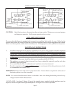
NOTE: FOR PROPER COMBUSTION, MAKE
SURE UNITS ARE LEVEL FRONT TO BACK
AND SIDE TO SIDE.
Page 8
35,000 - 80-3/16”
50,000 - 82-7/8”
55,000 - 88-7/8”
65,000 - 88-7/8”