


INTRODUCTION
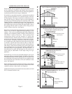
THIS IS A GAS-FIRED, GRAVITY VENTED WALL FURNACE THAT WILL OPERATE SAFELY AND PROVIDE AN EFFICIENT
SOURCE OF HEAT WHEN INSTALLED, OPERATED AND MAINTAINED AS RECOMMENDED IN THESE INSTALLATION
AND OPERATING INSTRUCTIONS. READ THESE INSTRUCTIONS THOROUGHLY BEFORE INSTALLING, SERVICING, OR
USING THE APPLIANCE. IF YOU DO NOT UNDERSTAND ANY PART OF THESE INSTRUCTIONS CONSULT LOCAL
AUTHORITIES, OTHER QUALIFIED INSTALLERS, SERVICE AGENCIES, THE GAS SUPPLIER, OR THE MANUFACTURER.
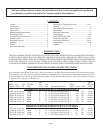
COUNTERFLOW WALL FURNACE SPECIFICATIONS
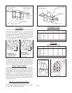
Your counterflow wall furnace is packed in a single carton that also includes thermostat, thermostat wire, and insulated staples.
The thermostat, wire, and staples are packed in the burner compartment and are accessible by removing the burner access door.
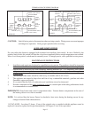
While the burner access door is open, check the rating plate to verify that the model number is correct and that the wall furnace
is equipped for the type gas you intend to use.
Vent Approx.
Model Type Type BTU/HR. Size Gas Blower Shipping
Number Control Gas Input (Oval) Inlet Finished Dimensions Speed Amps CFM Weight
MODELS WITH LOW-BTU STANDING PILOT
CF353C-H 24 Volt Nat. 35,000 4” ½” 14-5/16”Wx10¼”Dx78-5/8”H 1 1.95 320 95 Lbs.
CF354C-H 24 Volt L.P. 35,000 4” ½” 14-5/16”Wx10¼”Dx78-5/8”H 1 1.95 320 95 Lbs.
CF503C-H 24 Volt Nat. 50,000 4” ½” 14-5/16”Wx10¼”Dx81-5/16”H 2 2.25 440 104 Lbs.
CF504C-H 24 Volt L.P. 50,000 4” ½” 14-5/16”Wx10¼”Dx81-5/16”H 2 2.25 440 104 Lbs.
CF653C-H 24 Volt Nat. 65,000 4” ½” 14-5/16”Wx10¼”Dx87-5/16”H 2 2.25 440 107 Lbs.
CF654C-H 24 Volt L.P. 65,000 4” ½” 14-5/16”Wx10¼”Dx87-5/16”H 2 2.25 440 107 lbs.
MODELS WITH INTERMITTENT IGNITION
CF357C-H 24 Volt Nat. 35,000 4” ½” 14-5/16”Wx10¼”Dx78-5/8” H 1 2.2 320 95 Lbs.
CF358C-H 24 Volt L.P. 35,000 4” ½” 14-5/16”Wx10¼”Dx78-5/8”H 1 2.25 320 95 Lbs.
CF557C-H 24 Volt Nat. 55,000 4” ½” 14-5/16”Wx10¼”Dx87-5/16”H 2 2.5 440 107 Lbs.
CF558C-H 24 Volt L.P. 55,000 4” ½” 14-5/16”Wx10¼”Dx87-5/16”H 2 2.55 440 107 Lbs.
Page 2
CONTENTS
Contents……………………………………………........... 2
Introduction…………………………………………. 2
Specifications……………………………………….. 2
Safety Rules………………………………………… 3
Helpful Installation Information……………….........…. 3
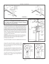
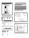
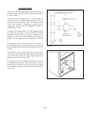
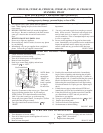
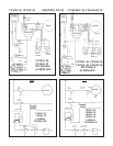
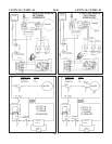
Connecting the Vent……………………………....…..… 3,4
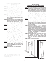
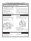
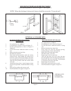
Combustion and Ventilation Air...................................... 5
Furnace Location………………………………….....…. 6
Rough-In Instructions…………………………..…..…. 6,7
Installation……………………………………….......….. 8
Controls…………………………………………........….. 9
Pilot Flame Adjustment…………………………......….. 9
Lighting & Re-Lighting Instructions……………….. 10,11
Operation………………………………………….....…. 12
Terminal Block Wiring Diagram……………….....…… 13
Manual Reset…………………………………....…….. 13
Maintenance Instructions…………………….……… 13
Wiring Diagram……………………………….....…….. 14,15
Side & Rear Discharge Kits……………………...……16,17
Trouble Shooting Chart…………………………..….. 18,19
Repair Parts (break down)………………………..….. 20-24
Repair Parts List…………………………………....…. 21-25
Warranty………………………………………….....…. 27
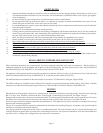
The State of Massachusetts requires that installation and service of a gas appliance be performed
by a plumber or gas fitter licensed in the Commonwealth of Massachusetts.