


GAS ROUGH-IN
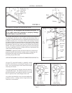
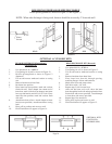
Check local codes for requirements as to the size and type of
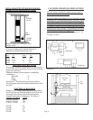
gas line required. See Figure 5 for location of gas inlet holes
in furnace cabinet.
Compounds used on threaded joints of gas pipe should be
resistant to the action of liquefied petroleum gases. The gas
line joints must be checked for leaks. This should be done
with a soap solution – watching for bubbles on all
connections. NEVER USE AN EXPOSED FLAME TO
CHECK FOR LEAKS.
A manual valve equipped with a 1/8” NPT plugged tapping
accessible for test gauge connection should be installed
immediately upstream of the gas supply connection to the
appliance. Some codes and ordinances require that the
manual valve be located outside the appliance. See Figure
4.
The appliance and its individual shut off valve must be
disconnected from the gas supply piping system during any
pressure testing of that system at test pressures in excess of
½ psig.
The appliance must be isolated from the gas supply piping
system by closing its individual manual shut off valve during
any pressure testing of the gas supply piping system at test
pressures equal to or less than ½ pig.
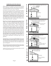
It is required by the National Fuel Gas Code that a drip line
be installed near the gas inlet. This should consist of a vertical
length of pipe tee connected into the gas line that is capped
on the bottom in which condensation and foreign particles
may collect.
Page 7
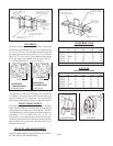
1-1/2” Dia.
Knockout
1-1/2” Dia.
Gas Inlet
Hole
4”
8”
5”
2”
FIGURE 5
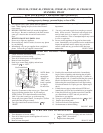
FIGURE 4
Drip
Leg
Manual cut off valve
1/8 N.P.T.
Pressure Tap
Gas
Supply
Line
To heater gas control valve