


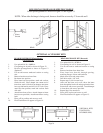
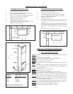

SIDE DISCHARGE ON CASING
1. Use optional kit No. 306SR-A.
2. Cut out and remove embossed area on casing side.
3. Remove knockout from inner liner.
4. Place 1-1/2” boot from kit through opening, matching
flanges of boot to knockout on inner boot.
5. Mark screw holes and remove boot.
6. Drill holes with a 1/8” drill.
7. Attach inner boot with screws provided.
8. Place grille into position, drill holes into casing, and
attach with screws provided.
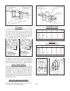
SIDE DISCHARGE (With Extension Boot)
1. Use optional kit No. 30SRB-A.
2. Cut opening in drywall as shown in Fig. 17.
3. Position plasterground as shown in Fig. 17 (optional).
4. Cut out and remove embossed section on casing side.
5. Remove knockout on inner liner.
6. Put heater into position.
7. Place inner boot into position, mark and cut boot flush with
wall. Place outer boot into position, mark and cut boot flush
with wall.
8. Place boot trim into position, slide inner boot through wall
from adjacent room and attach to inner liner. Slide outer
boot through wall from adjacent room and attach to casing
side.
9. Place grille into position and secure to wall.
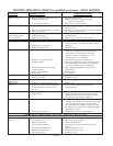
OPTIONAL KITS - CONTINUED
18”
Min.
FIGURE 16
FIGURE 17
MODEL Length of bottom section
NUMBER (Ref. 4) plastic raceway
CF35 5-5/16 Inches
CF50 8 Inches
CF55 14 Inches
CF65 14 Inches
NOTE: Above lengths terminate
approximately 2 inches above floor.
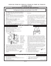
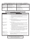
14PEK-A PLUG EXTENSION KIT INSTRUCTIONS
FOR NON-RECESSED INSTALLATION ONLY
UNITS WITH TERMINAL BOARD
STEP 1. Turn heater off following Section 3 in “Lighting Instructions” and allow
to cool.
STEP 2. Turn off all electricity to heater.
STEP 3. Remove top louver assembly, fan shroud and fan blade.
STEP 4. Loosen two screws on romex connector.
STEP 5. Remove junction box cover plate.
STEP 6. Disconnect three power cord terminals and pull power cord out of top
of heater.
STEP 7. Insert power cord provided in kit through romex connector and plug
onto terminal board following wiring diagram found in lighting and
operating instructions.
STEP 8. Tighten two screws on romex connector.
STEP 9. Replace junction box cover plate.
STEP 10. Replace fan blade, fan shroud and top louver assembly.
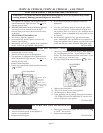
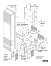
STEP 11. Snap 90 Degree outside corner (Ref. 1) onto 3 ft. section (Ref. 2)
plastic raceway. Insert power cord and remove blue backing from
adhesive strip on raceway and apply to side of heater. See Figure 18.
STEP 12. Insert power cord into second 3 ft. section of raceway (Ref. 3) and
remove blue backing and apply to side of heater, butting up agianst
bottom of other section. See Fig. 18.
STEP 13. Cut 14 inch long bottom section to required length (see chart), insert
power cord, remove backing and apply to side of heater. See Fig. 18.
STEP 14. Plug power cord into wall receptacle, see Fig.18.
STEP 15. Light the heater following lighting instructions.
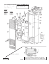
FI
GU
RE
18
90
De
gr
ee
Outside Corner
3 F
T.
SECTION
3 F
T.
SECTION
BO
TT
OM
SE
CT
IO
N
WA
LL
Page 17