


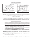
LOCATION AND SPECIAL PRECAUTIONS
The wall furnace should be located near the center of
the house for best heat distribution.
If the area where the appliance is to be installed contains
carpeting, tile or combustible materials, other than wood
flooring, the appliance shall be installed on a metal plate,
wood panel or other non-combustible materials. The use
of ceramic or quarry tile is acceptable and will provide a
surface that is easily cleaned. This material is to extend
the full width and depth of the appliance. If side or rear
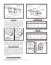
warm air outlets are being installed, see figure 14 – 18,
See page 16 and 17.
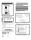
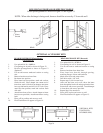
ROUGH-IN INSTRUCTIONS
In selecting a location for installation, it is necessary to
provide adequate accessibility clearances for servicing
and proper operation.
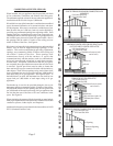
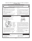
Minimum clearance from cabinet to combustible
construction:
Side Wall - 4”
Floor - 0”
Ceiling - 4”
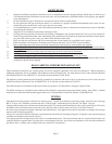
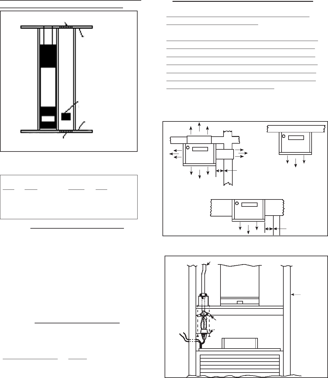
See Figure 2. The unit may be recessed and rest
directly against side studs and the inside surface of the
rear wall.
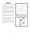
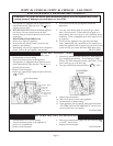
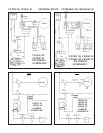
ELECTRICAL ROUGH-IN
Rough in 115 v. wiring, terminating inside the junction
box located on top of header plate for recessed, or in
a receptacle box (not provided) for flush mount.
Consult local codes or ordinances. See Figure 3.
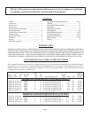
MODEL NUMBER AMPS
CF353C, CF354C 1.95
CF503C, CF504C 2.25
CF653C, CF654C 2.25
CF357C 2.2
CF358C 2.25
CF557C 2.5
CF558C 2.55
4” Minimum
4” Minimum
FIGURE 2
Page 6
115 V.A.C.
Line
In
B-W Vent
Pipe
2x4
Stud
Header Plate
Wire Nut (not provided)
Switch Box Cover Plate
FIGURE 3
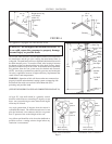
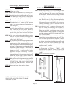
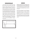
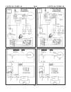
USING ADJACENT STUD SPACE FOR ALL
COMBUSTION AIR FROM OUTSIDE
HOLES CONNECTING TO
VENTILATED ATTIC
CEILING
PLATE
AIR
GRILLE
FLOOR
PLATE
HOLES CONNECTING TO VENTILATED
CRAWL SPACE
BASED ON 4,000 BTU OF TOTAL INPUT RATING
OF ALL GAS APPLIANCES, THE HEATER ONLY
REQUIRES A MINIMUM FREE AREA OF:
SQUARE HOLE SQUARE
BTU IN. SIZE = IN.
25,000 6.25 1” .785
35,000 8.75 1.5” 1.76
50,000 12.50 2” 3.14
55,000 13.75 2.5” 4.90
65,000 16.25 3” 7.065