


Version 2.0b 17
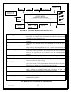
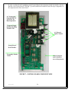
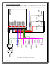
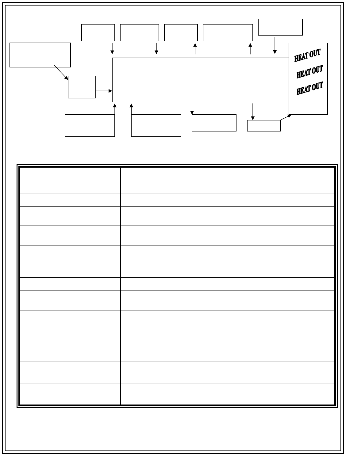
FIGURE 3: CONTROL BOARD BLOCK DIAGRAM
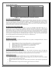
Input Voltage
Alternating Current (AC) Input provided by the local power company. This source of energy
must provide a 120 Volt input signal with a frequency of 60 Hertz and a maximum branch
current capacity of 15 Amperes. If other devices are connected to the branch, interference or
over current may cause circuit breaker to trip.
Fuse
The AC fuse should be rated between 6 and 9 amperes. The recommended fuse is a Little
Fuse Model _______.
Vacuum Sensor
Ensures that no blockage of the combustion input or combustion exhaust air occurs. If the
vacuum sensor does not operate properly, the Control Board will not allow the stove to
operate.
Exhaust Temperature Sensor
Presently, this sensor is a snap disk operating at 110
o
F +/- 20
o
F. This sensor ensures proper
exhaust temperature has been reached and that a fire is present in the burn pot before the
control system begins the burn cycle.
Room Air Temperature Sensor
Presently, this sensor is a snap disk operating at 110
o
F +/- 20
o
F. This sensor ensures that a
proper amount of heat is available at the heat exchanger before the room fan is allowed to
operate. If the sensor allows the fan to come on to early, the combustion chambers
temperature could drop to the point that self-combustion (ignition temperatures) cannot be
maintained.
Overtemp Sensor
Presently, this sensor is a snap disk operating at 250
o
F +/- 20
o
F. The purpose of this sensor
is to shut the entire system down in the event the firebox causes an overheat condition.
Fuel Control
The fuel control is a signal provided from the Control Board to the Auger Feed Motor. The
Control Board controls the amount of time that the Auger Feed Motor is on and thereby
controls the amount of fuel fed to the fire pot.
Room Air Control
The room air control is a signal provided from the Control Board to the Room Air Fan. The
Control Board controls the phase angle and thereby the amount and time an AC voltage is
applied to the Room Air Fan. This signal controls the speed of the room air passing over the
heat exchanger tubes and the amount of heat delivered to the living space.
Combustion Air Control
The combustion air control is a signal provided from the Control Board to the Combustion
Fan. The Control Board controls the phase angle and thereby the amount and time an AC
voltage is applied to the Combustion Air Fan. This signal controls the speed of the
combustion air passing through the burn pot for the different heat settings
Igniter
An AC heating element used to provide initial heat to the pellet combustion process. Once
the Control Board senses combustion, the Igniter is shut off to conserve energy usage.
Thermostat (optional)
A thermostat input is provided on the back of each Country Flame product. The Control
Board has individual personality modules that allow for stand-alone, semi automatic, or fully
automatic thermostat operation.
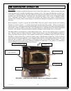
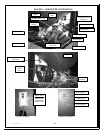
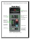
FIGURE 4: STOVE COMPONENT DEFINITIONS
STOVE
INPUT VOLTAGE
120 Volts AC 60 Hz
15-Ampere Circuit
Fuse
6 – 9
Amperes
CONTROL BOARD
ON/OFF SWITCH
TEMPERATURE CONTROL
POWER/FUEL/IGNITER/ INDICATORS
VACUUM
SENSOR
EXHAUST
TEMPERATURE
SENSOR
ROOM AIR
TEMPERATURE
SENSOR
OVERTEMP
SENSOR
FUEL
CONTROL
COMBUSTION
AIR CONTROL
ROOM AIR
CONTROL
IGNITER
THERMOSTAT
(Optional)