


W415-0327 / B / 12.07.07
6
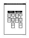
Use only Wolf Steel, Simpson Dura-Vent, Selkirk Direct Temp or
American Metal Amerivent venting components.Minimum and
maximum vent lengths, for both horizontal and vertical installations,
and air terminal locations for either system are set out in this manual
and must be adhered to. For Simpson Dura-Vent, Selkirk Direct Temp
and American Metal Amerivent, follow the installation procedure
provided with the venting components.
All outer pipe joints of these venting systems must be sealed using
Red RTV Hight Temperature Sealant.
Wolf Steel, Simpson Dura-Vent, Selkirk Direct Temp and American
Metal Amerivent venting systems must not be combined.
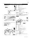
A starter adaptor must be used and may be purchased from the
corresponding supplier:
Supplier 5&8 ZC
Dura-Vent W175-0170
Amerivent 4DSC-N2
Direct Temp 5DT-AA
For Simpson Dura-Vent, Selkirk Direct Temp and American
Metal Amerivent, follow the installation procedure found on
the website for your venting supplier:
VENTING SUPPLIER WEBSITE ADDRESS
Simpson Dura-Vent www.duravent.com
Selkirk Direct Temp www.selkirkcorp.com
American Metal Amerivent www.americanmetalproducts.com
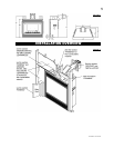
When using Wolf Steel venting components, use only approved Wolf
Steel rigid / fl exible components with the following termination kits:
WALL TERMINAL KIT GD422, or 1/12 TO 7/12 PITCH ROOF TER-
MINAL KIT GD410, 8/12 TO 12/12 ROOF TERMINAL KIT GD411,
FLAT ROOF TERMINAL KIT GD412 or PERISCOPE KIT GD401 (for
wall penetration below grade). With fl exible venting, in conjunction
with the various terminations, use either the 5 foot vent kit GD420
or the 10 foot vent kit GD430.
It is recommended to attach the Wolf Steel 45º rigid adaptor
directly to the unit when terminating horizontally off the back
of the unit. This must be done before attaching the desired vent
system. Once this transition has been made, venting systems
must not be combined.
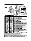
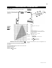
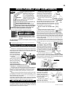
These vent kits allow for either horizontal or vertical venting of the
fi replace. FIGURES 3 & 4. The maximum allowable horizontal run is
20 feet. The maximum allowable vertical vent length is 40 feet. The
maximum number of 5" vent connections is two horizontally or three
vertically (excluding the fi replace and the air terminal connections)
when using aluminium fl exible venting.
When terminating vertically, restrictor plate W500-0205 must be
installed. (Refer to Restricting Vertical Vents).
For optimum flame appearance and fireplace performance,
keep the vent length and number of elbows to a minimum.
The air terminal must remain unobstructed at all times. Ex-
amine the air terminal at least once a year to verify that it is
unobstructed and undamaged.
Purge all gas lines with the glass door of the fireplace removed.
Assure that a continuous gas flow is at the burner before re-
installing the door.
Under extreme vent configurations, allow several minutes (5-15)
for the flame to stabilize after ignition.
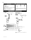
VENTING
VENTING LENGTHS
For safe and proper operation of the fi replace follow the venting instruction exactly. Deviation from the minimum vertical vent length can
create diffi culty in burner start-up and/or carboning. Provide a means for visually checking the vent connection to the fi replace after the
fi replace is installed. Vent lengths that pass through unheated spaces (attic, garages, crawl spaces) should be insulated with the insulation
wrapped in a protective sleeve to minimize condensation.
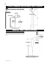
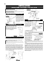
HORIZONTAL VENT SECTIONS: A minimum clearance of 2" all
around the vent pipe in all horizontal runs to combustibles is required.
Use fi restop spacer W010-1778 (supplied).
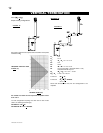
VERTICAL VENT SECTIONS: A minimum of 1" all around the vent
pipe on all vertical runs to combustibles is required. Use fi restop
spacer W500-0028 (not supplied)
.
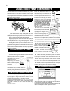
Horizontal runs may have a 0" rise per foot in all cases using
Wolf Steel rigid or flexible vent components or Simpson
Dura-Vent, Selkirk Direct Temp or American Metal Amerivent
vent components.
For optimum performance it is recommended that all horizontal
runs have a 1" rise per foot when using Wolf Steel flexible vent
components.
A terminal shall not terminate directly above a sidewalk or
paved driveway which is located between two single family
dwellings and serves both dwellings. Local codes or regulations
may require different clearances.
Do not allow the inside liner to bunch up on horizontal or ver-
tical runs and elbows. Keep it pulled tight. A 1¼" air gap all
around between the inner liner and outer liner is required for
safe operation. Use a firestop when penetrating interior walls,
floor or ceiling.