


W415-0327 / B / 12.07.07
14
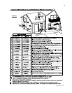
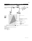
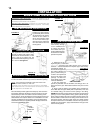
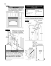
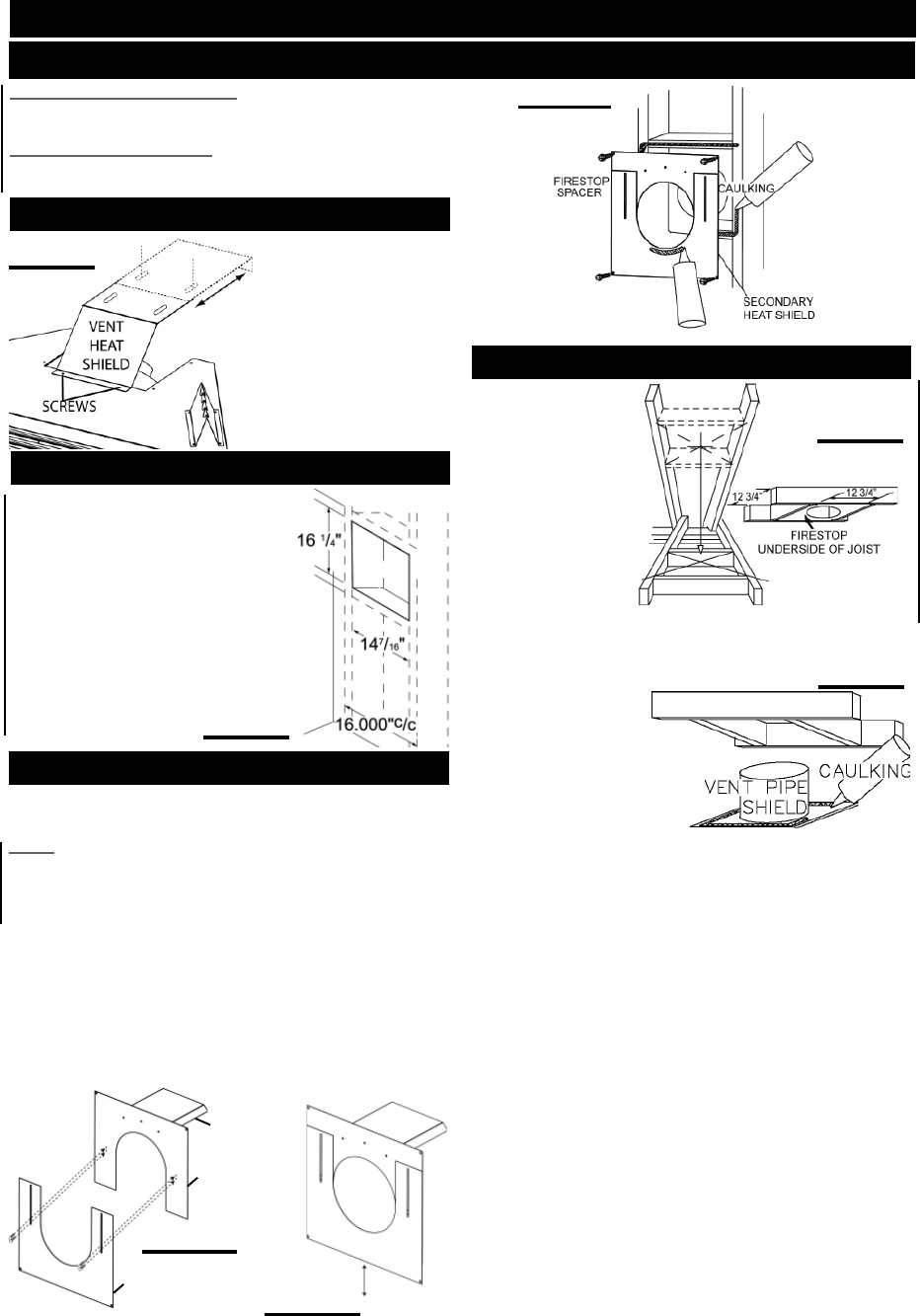
FIGURE 16
This application occurs
when venting through
a roof. Installation kits
for various roof pitches
are available from your
Continental® dealer. See
Accessories to order the
specifi c kit required.
1. Determine the air
terminal location, cut and frame
12
3
/
4
" x 12
3
/
4
" openings in the ceiling and the roof to provide the
minimum
1" clearance between the fi replace pipe / liner and any
combustible material. Try
to centre the vent pipe loca-
tion midway between two
joist to prevent having to
cut them. Use a plumb bob
to line up the centre of the
openings. DO NOT FILL
THIS SPACE WITH ANY
TYPE OF MATERIAL.
A vent pipe shield will
prevent any materials such as insulation, from fi lling up the 1" air
space around the pipe. Nail headers between the joist for extra
support.
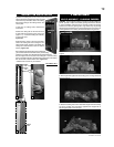
2. Apply a bead of caulking (not supplied) to the framework or
to the Wolf Steel vent pipe shield plate or equivalent (in the case
of a fi nished ceiling), and secure over the opening in the ceiling.
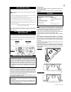
FIGURE 19. A fi restop must be placed on the bottom of each framed
opening in a roof or ceiling that the venting system passes through.
Apply a bead of caulking all around and place a fi restop spacer over
the vent shield to restrict cold air from being drawn into the room or
around the fi replace. Ensure that both spacer and shield maintain
the required clearance to combustibles. Once the vent pipe / liner is
installed in its fi nal position, apply sealant between the pipe / liner
and the fi restop spacer.
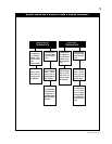
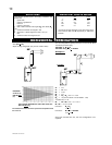
HORIZONTAL INSTALLATION
VERTICAL INSTALLATION
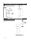
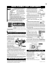
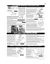
FIGURE 18
INSTALLATION
WALL AND CEILING PROTECTION
VENT HEAT SHIELD INSTALLATION
The vent heat shield must be
installed only when terminat-
ing horizontally with no vertical
rise. Remove the two screws
nearest the vent collars on
the top of the fi replace. Align
the vent heat shield (sup-
plied) and secure. Adjust the
vent heat shield to touch the
fi restop spacer.
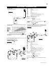
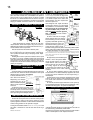
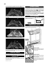
ADJUSTABLE FIRESTOP INSTALLATION
FIGURE 17c
Apply a bead of caulking all around and place the fi restop top, so
that the vent shield covers the top of the vent within the opening.
NOTE: THE FIRESTOP ASSEMBLY MUST BE INSTALLED
WITH THE VENT SHIELD TO THE TOP.
The length of the vent shield may be cut shorter for combustible
walls that are less than 8 1/2" thick but the vent shield must extend
the full depth of the combustible wall.
Place the fi restop bottom against the fi restop top and secure the
two together. Adjust the assembly to ensure it is tight to the vent.
Secure fi restop to wall. This restricts cold air from being drawn
into the room or around the fi replace. Ensure that both spacer and
shield maintain the required clearance to combustibles. Once the
vent pipe is installed in its fi nal position, apply high temperature
sealant W573-0002 (not supplied) between the pipe and the fi re-
stop spacer. See fi gures 17a-c.
FIGURE 17b
VENT
SHIELD
FIRESTOP
TOP
FIRESTOP
BOTTOM
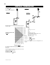
This application occurs when venting
through an exterior wall. Having deter-
mined the air terminal location, cut and
frame a hole in an exterior wall. The
recommended framed opening is 14
7
/16"
W x 16
1
/4" H. See fi gure16.
FIGURE 19
FIGURE 15
HORIZONTAL VENT SECTIONS: A minimum clearance of 2" all
around the vent pipe in all horizontal runs to combustibles is required.
Use fi restop spacer W010-1778 (supplied).
VERTICAL VENT SECTIONS: A minimum of 1" all around the vent
pipe on all vertical runs to combustibles is required. Use fi restop
spacer W500-0028 (not supplied).
FIGURE 17a