


W415-0327 / B / 12.07.07
16
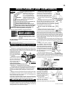
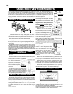
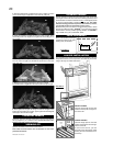
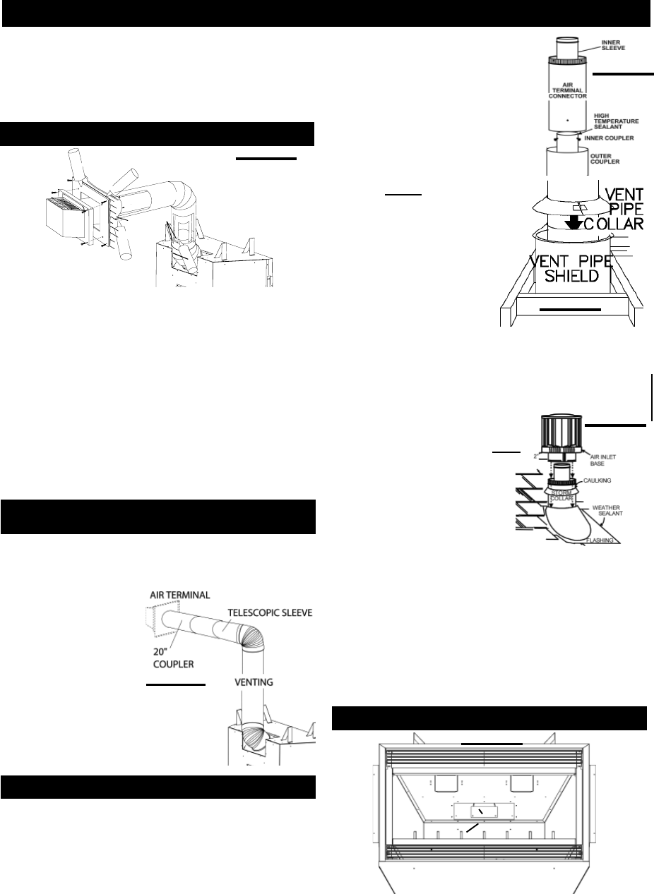
FIGURE 31
RESTRICTOR PLATE
TOP OF THE
FIREBOX
FLUE COLLAR
The vent system must be supported approximately every 3 feet for
both vertical and horizontal runs. Use Wolf Steel vent spacers or
equivalent every 3 feet and either side of each elbow to maintain
the minimum 1¼" clearance between the outer and inner vent pipes.
Use Wolf Steel support ring assembly or equivalent noncombustible
strapping to maintain the minimum clearance to combustibles for
both vertical and horizontal runs.
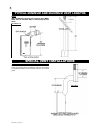
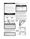
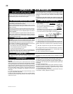
1. Move the fi replace into position. Measure the vent length
required between terminal and fi replace taking into account the
additional length needed for the fi nished wall surface and any 1¼"
overlaps between venting components.
2. Secure the terminal to the terminal extension plate.
3. Apply high temperature sealant W573-0007 (not supplied) to
the outer edge of the 5" inner collar of the fi replace. Attach the fi rst
vent component and secure using 3 self tapping screws. Repeat
using 8" piping.
4. Holding the air terminal (with the air defl ectors to the top and
the lettering in an upright, readable position) insert into both vent
pipes with a twisting motion to ensure that both the terminal sleeves
engage into the vent pipes and sealant. Secure the terminal exten-
sion plate to the exterior wall and make weather tight by sealing with
caulking (not supplied).
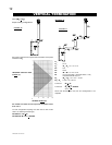
FIGURE 28
USING RIGID VENT COMPONENTS
HORIZONTAL AIR TERMINAL INSTALLATION
EXTENDED HORIZONTAL AIR TERMINAL
INSTALLATION
H
H
I
I
-
-
T
T
E
E
M
M
P
P
S
S
E
E
A
A
L
L
A
A
N
N
T
T
8
8
"
"
P
P
I
I
P
P
E
E
2
2
"
"
O
O
V
V
E
E
R
R
L
L
A
A
P
P
5
5
"
"
P
P
I
I
P
P
E
E
C
C
A
A
U
U
L
L
K
K
I
I
N
N
G
G
T
T
E
E
R
R
M
M
I
I
N
N
A
A
L
L
E
E
X
X
T
T
E
E
N
N
S
S
I
I
O
O
N
N
P
P
L
L
A
A
T
T
E
E
S
S
C
C
R
R
E
E
W
W
S
S
#
#
1
1
0
0
x
x
2
2
½
½
"
"
C
C
A
A
U
U
L
L
K
K
I
I
N
N
G
G
S
S
E
E
A
A
L
L
A
A
N
N
T
T
H
H
I
I
-
-
T
T
E
E
M
M
P
P
A
A
T
T
T
T
E
E
N
N
T
T
I
I
O
O
N
N
-
-
C
C
H
H
A
A
U
U
D
D
C
C
A
A
U
U
T
T
I
I
O
O
N
N
-
-
H
H
O
O
T
T
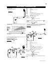
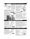
FIGURE 27
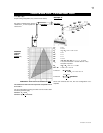
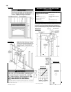
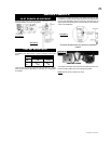
FIGURE 30
VERTICAL VENTING INSTALLATION
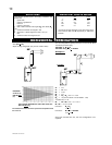
FIGURE 29
1. Follow the instructions for "Horizontal Air Terminal Installations",
items 1 to 4.
2. Continue adding components alternating inner and outer venting.
Ensure that all 5" venting and elbows have suffi cient vent spacers
attached and each component
is securely fastened to the one
prior. Attach the 5" telescopic
sleeve to the vent run.
Repeat using a 8" telescopic
sleeve. Secure and seal as
before. To facilitate completion,
attach 5" and 8" couplers to the
air terminal.
3. Install the air terminal. See item 4 of the
Horizontal Air Terminal Installation. Extend the
5" telescopic sleeve; connect to the air terminal
assembly. Fasten with self tapping screws and
seal. Repeat using the 8" telescopic sleeve.
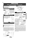
1. Move the fi replace into position.
2. Fasten the roof support to the roof using the screws provided.
The roof support is optional. In this case the venting is to be ad-
equately supported using either an alternate method suitable to the
authority having jurisdiction or the optional roof support.
3. Apply high temperature sealant
W573-0002 (not supplied) to the
outer edge of the inner sleeve of the air terminal. Slip a 5" diam-
eter coupler a minimum of 2" over the sleeve and secure using 3
screws.
4. Apply high temperature sealant W573-
0002 (not supplied)
to the outer edge of the
of the outside sleeve of the air terminal. Slip
a 8" diameter coupler over the sleeve and
secure as before. Trim the 8" coupler even
with the 5" coupler end.
5. Thread the air terminal pipe assembly
down through the roof support and attach,
ensuring that a minimum 16" of air terminal
will penetrate the roof when fastened. If the
attic space is tight, we recommend thread-
ing the Wolf Steel vent pipe collar or
equivalent loosely onto the air terminal
assembly as it is passed through the
attic. The air terminal must be located
vertically and plumb.
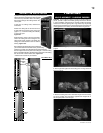
6. Remove nails from the shingles,
above and to the sides of the chimney.
Place the fl ashing over the air terminal
and slide it underneath the sides and
upper edge of the shingles. Ensure
that the air terminal is properly cen-
tred within the fl ashing, giving a 3/4"
margin all around. Fasten to the roof.
Do NOT nail through the lower portion of the fl ashing. Make weather-
tight by sealing with caulking. Where possible, cover the sides and
top edges of the fl ashing with roofi ng material.
7. Aligning the seams of the terminal and air terminal connector,
place the terminal over the air terminal connector making sure the
inner sleeve goes into the hole in the terminal. Secure with the 3
screws provided.
8. Apply a heavy bead of weatherproof
caulking 2" above the flashing. Note:
Maintain a minimum 2" space between
the air inlet base and the storm collar.
Install the storm collar around the air
terminal connector and slide down to
the caulking. Tighten to ensure that
a weather-tight seal between the air
terminal connector and the collar is
achieved.
9. Continue adding rigid venting sections, sealing and securing
as above. Attach a 5" collapsed telescopic pipe to the last section
of rigid piping. Secure with screws and seal. Repeat using a 8"
telescopic pipe.
10. Run a bead of high temperature sealant around the outside
of the 5" collar on the fi replace. Pull the adjustable pipe a minimum
of 2" onto the collar. Secure with 3 screws. Repeat with the 8" tel-
escopic pipe.
11. In the attic, slide the vent pipe collar down to cover up the open
end of the shield and tighten. This will prevent any materials, such as
insulation, from fi lling up the 1" air space around the pipe.
Vertical terminations display a very active fl ame. The vent exit must
be restricted using restrictor plate, W500-0205.
Remove the two screws on either side of the exhaust collar inside the
fi rebox. Install the plate as shown. Replace the screws.
RESTRICTING VERTICAL VENTS
FIGURE 32