


W415-0327 / B / 12.07.07
15
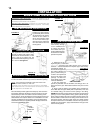
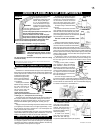
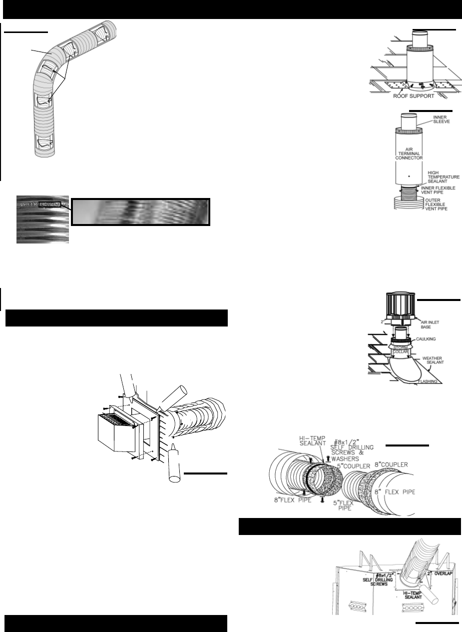
FIGURE 25
4. Insert the vent pipe assembly through the fi restop maintaining
the required clearance to combustibles. Holding the air terminal
(lettering in an upright, readable position), secure to the exterior
wall and make weather tight by sealing with caulking (not sup-
plied).
5. Apply a heavy bead of the high temperature sealant, W573-0007
(not supplied) to the inside of the 5" vent pipe approximately 1" from
the end. Slip the vent pipe a minimum of 2" over the fi replace vent
collar and secure with 3 #8 screws.
ELBOW
SPACERS
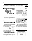
FIGURE 20
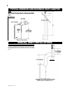
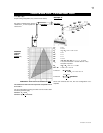
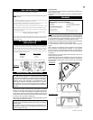
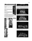
1. Secure the terminal to the terminal extension plate (see fi gure
21).
2. Stretch the 5" diameter fl exible vent pipe to the required length
taking into account the additional length needed for the fi nished wall
surface. Slip the liner a minimum of 2" over the inner sleeve of the
air terminal and secure with
3 #8 screws. Apply a heavy
bead of the high tempera-
ture sealant W573-0002
(not supplied).
3. Using the 8" diameter
fl exible vent pipe, slide over
the outer combustion air
sleeve of the air termi-
nal and secure with 3 #8
screws. Seal as before.
The air terminal mounting
plate may be recessed into the exterior wall
or siding by 1½", the depth of the return fl ange.
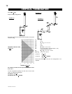
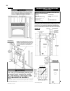
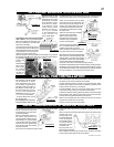
2. Stretch the 5" fl exible vent pipe to
the required length. Slip the vent pipe a
minimum of 2" over the inner sleeve of
the air terminal connector and secure
with 3 #8 screws. Seal using a heavy
bead of the high temperature sealant.
3. Repeat using 8" diameter fl exible
vent pipe.
4. Thread the air terminal connector/
pipe assembly down through the roof. The air
terminal must be located vertically and plumb.
Attach the air terminal connector to the roof sup-
port, ensuring that a minimum 16" of air terminal
will penetrate the roof when fastened.
DO NOT CLAMP THE FLEXIBLE VENT
PIPE.
Use only approved flexible vent pipe kits marked:
"Wolf Steel Approved Venting" as iden-
tified by the stamp only on the 8” outer
vent pipe.
For safe and proper operation of the fireplace, follow the venting
instructions exactly.
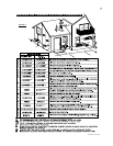
USING FLEXIBLE VENT COMPONENTS
HORIZONTAL AIR TERMINAL INSTALLATION
C
C
A
A
U
U
L
L
K
K
I
I
N
N
G
G
T
T
E
E
R
R
M
M
I
I
N
N
A
A
L
L
E
E
X
X
T
T
E
E
N
N
S
S
I
I
O
O
N
N
P
P
L
L
A
A
T
T
E
E
S
S
C
C
R
R
E
E
W
W
S
S
#
#
1
1
0
0
x
x
2
2
½
½
"
"
C
C
A
A
U
U
L
L
K
K
I
I
N
N
G
G
8
8
"
"
F
F
L
L
E
E
X
X
S
S
E
E
A
A
L
L
A
A
N
N
T
T
H
H
I
I
-
-
T
T
E
E
M
M
P
P
2
2
"
"
O
O
V
V
E
E
R
R
L
L
A
A
P
P
P
P
I
I
P
P
E
E
5
5
"
"
F
F
L
L
E
E
X
X
P
P
I
I
P
P
E
E
A
A
T
T
T
T
E
E
N
N
T
T
I
I
O
O
N
N
-
-
C
C
H
H
A
A
U
U
D
D
C
C
A
A
U
U
T
T
I
I
O
O
N
N
-
-
H
H
O
O
T
T
FIGURE 21
FIGURE 22
FIGURE 23
5. Remove nails from the shingles, above and
to the sides of the chimney. Place the fl ashing
over the air terminal and slide it underneath the
sides and upper edge of the shingles. Ensure
that the air terminal connector is properly centred within the fl ashing,
giving a 3/4" margin all around. Fasten to the roof. Do not nail through
the lower portion of the fl ashing. Make weather-tight by sealing with
caulking. Where possible, cover the sides and top edges of the fl ash-
ing with roofi ng material.
6. Aligning the seams of the terminal and air terminal connec-
tor, place the terminal over the air terminal connector making sure
the inner pipe goes into the hole in the terminal. Secure screws
provided.
7. Apply a heavy bead of weather-
proof caulking 2" above the fl ashing.
Note: Maintain a minimum 2" space
between the air inlet base and the storm
collar. Install the storm collar around the
air terminal and slide down to the caulk-
ing. Tighten to ensure that a weather-
tight seal between the air terminal and
the collar is achieved.
8. If more vent pipe needs to be used
to reach the fi replace, couple them together as illustrated in Figure
25. The vent system must be supported approximately every 3 feet
for both vertical and horizontal runs. Use noncombustible strapping
to maintain a clearance to combustibles of 1".
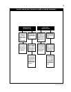
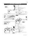
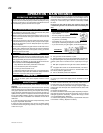
FIREPLACE VENT CONNECTION
FIGURE 26
FIGURE 24
6. Using the 8" diameter fl exible vent pipe, apply high temperature
sealant W573-0002 (not supplied), slide a minimum of 2" over the
fi replace combustion air collar and secure with 3 #8 screws.
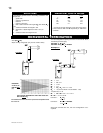
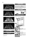
1. Fasten the roof support to the roof using the screws provided. The
roof support is optional. In this case the venting is to be adequately
supported using either an alternate method suitable to the authority
having jurisdiction or the optional roof support.
Do not allow the inside fl exible
vent pipe to bunch up on
horizontal or vertical runs and
elbows. Keep it pulled tight.
A 1 1/4" air gap between the
inner and the outer vent pipe
all around is required for safe
operation. A spacer is required
at the start, middle and end of each elbow to
ensure this gap is maintained.
For safe and proper operation of the fi replace, fol-
low the venting instructions exactly.
All inner exhaust and outer intake vent pipe
joints may be sealed using either Red RTV high
temp silicone sealant or Black high temp Mill
Pac with the exception of the fi replace exhaust fl ue collar
which must be sealed using Mill Pac (not supplied).
1. Install the 5" fl exible
vent pipe to the fireplace.
Secure with 3 screws and fl at
washers. Seal the joint and
screw holes using the high
temperature sealant W573-
0007 (not supplied).
2. Install the 8" flexible
vent pipe to the fireplace.
Attach and seal with high
temperature sealant W573-0002 (not supplied).
VERTICAL AIR TERMINAL INSTALLATION
NOTE: Eight (8”) inches is the minimum bend radius allowed for
the 8” diameter fl exible vent pipe.