


ENGLISH
5
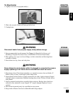
1. Remove all packing items applied to heater for shipment. Keep plastic cover caps
(attached to inlet connection and hose/regulator assembly) for storage.
2. Remove all items from carton.
3. Check all items for shipping damage. If heater is damaged, promptly inform dealer
where you bought heater.
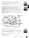
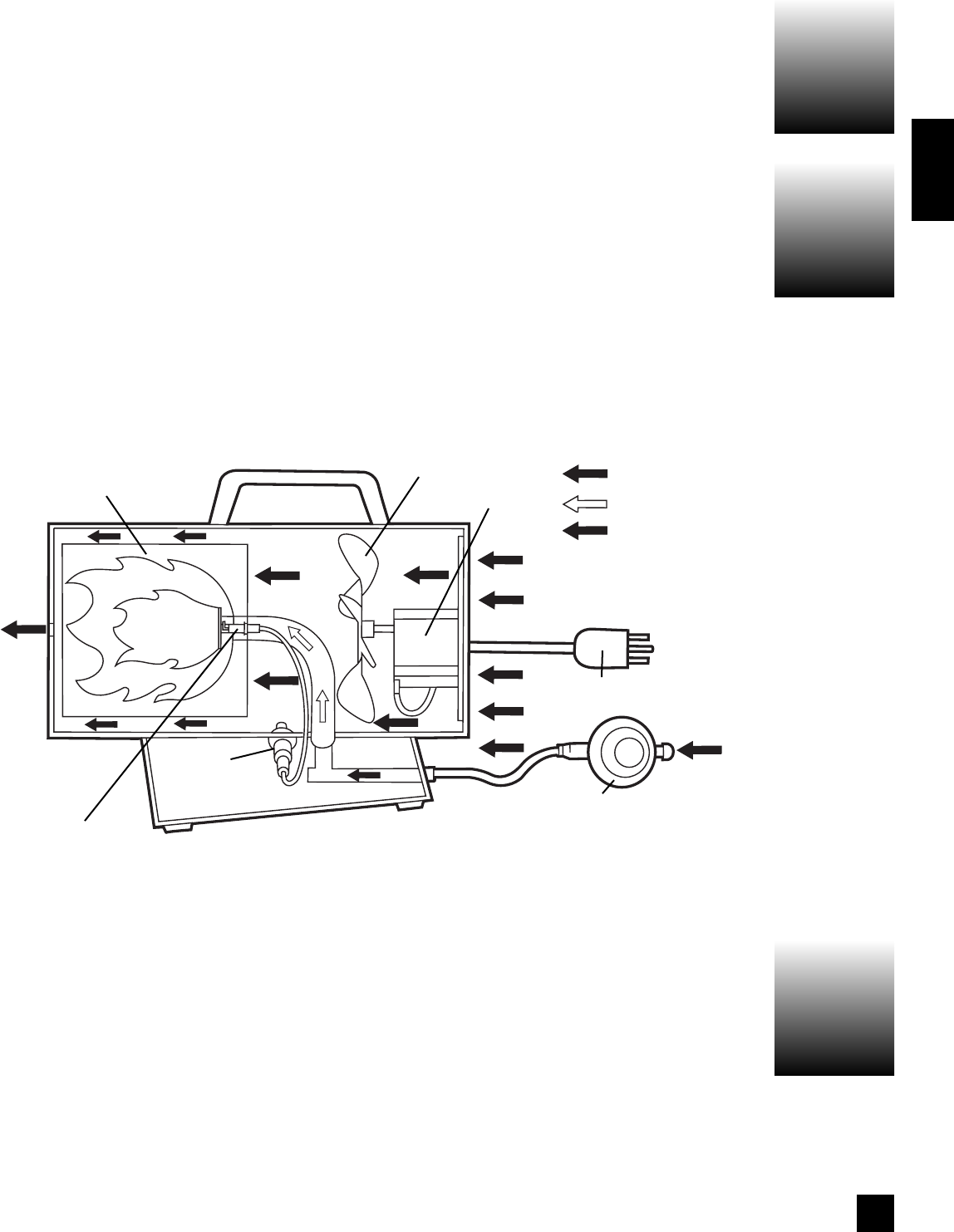
The Fuel System: The hose/regulator assembly attaches to the propane gas supply. The
propane gas moves through the thermoelectric valve and out the nozzle.
The Air System: The motor turns the fan. The fan pushes air into and around the com-
bustion chamber. This air is heated and provides a stream of clean, hot air.
The Ignition System: The piezo spark ignitor (Model 5070A) or Electronic Module
(Model 5075A) sends voltage to the electrode. The spark at the electrode ignites the fuel
air mixture.
The Safety Control System: This system causes the heater to shut down if the heater
overheats for any reason including loss of electric power. (The fan will continue to operate
if electric power is not lost.)
UNPACKING
THEORY OF
OPERATION
Propane Supply Information continues on next page
PROPANE
SUPPLY
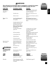
Propane gas and propane tank(s) are to be furnished by the user.
Use this heater only with a propane vapor withdrawal supply system. See Chapter 5 of the
Standard for Storage and Handling of Liquefied Petroleum Gas, ANSI/NFPA 58. Your local
library or fire department will have this booklet.
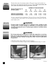
The amount of propane gas ready for use from propane tanks varies. Two factors decide
this amount:
1. The amount of propane gas in tank(s).
2. The temperature of tank(s)
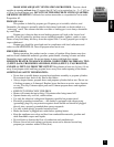
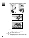
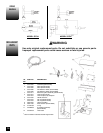
Cross Section Operational View (5070A Model Shown)
Fan
Motor
Cool Air In (Back)
Power Cord
Hose/Regulator
Assembly
Electrode
Clean Heated Air
Out (Front)
Combustion Chamber
Air For Heating
Combustion Air
Fuel
Ignitor