


21
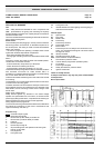
Operation
The gear-set draws oil from the tank through the built-in filter and transfers it to the valve that regulates the oil pressure or tne nozzle
line. All oil which does not go through the nozzle line will be dumped through the valve back to the return line or, if it is a one-pipe
installation, back to the suction port in the gear-set.
The hydraulic valve has a cut-off function besides regulating the nozzle pressure. Contrary to the AN pump, the valve has no bleed
slot. The function of the bleed slot is taken over by the solenoid valve. When the solenoid valve is non-activated, the by-pass channel
between the pressure and return sides of the valve is open. No pressure will then be built up to open the valve. It does not matter
which speed the gear set has. When the solenoid is activated, this by-pass channel will be closed and because of the full speed
of the gear set, the pressure necessary to open the valve will be built up very rapidly which gives a very sharp cut-on function.
When the burner stops, the solenoid opens the by-pass at the same moment which drains all the oil down to the return and the
nozzle valve closes immediately. This gives a very sharp cut-off function.
The cut-on and off can be regulated regardless of motor speed and has an extremely fast response. The torque requirement is low
up to full motor speed.
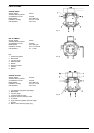
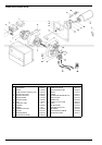
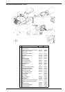
SUNTEC AT oil pumps
- Oil
- Twin-pipe system
- Single-pipe system
- Twin feed
Technical data
Mounting On hub Ø 32mm, in acccordance with
standards DIN 24220
Threads round-headed in accordance with ISO R
228-NFE 03005 (DIN259)
Supply and return R 1/4"
Delivery R 1/8"
Pressure R 1/8"
On cover R 1/8"
Valve function Pressure regulation
Filter Area 34 cm
2
,
mesh 120 micron
Shaft Ø 8 mm in acc. with DIN 24220
By-pass Insert for twin-pipe, remove for single-
pipe system
Weight 1,3 kg
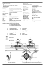
Rotation and delivery position (viewed from shaft side)
D - counterclockwise rotation/right delivery
C - counterclockwise rotation/left delivery
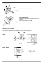
Hydraulic data
Operational pressure range to the nozzle
4 - 25 bar
Calibration 22 bars at factory
Viscosity at 20°C 2-12mm
2
/s (cSt)
Supply pressure max.2 bars
Return pressure max.2 bars
Suction max. vacuum 0,35 bars,
recommended to
avoid separation of oil and gas
Rotational speed 3600 rpm
Max. oil temperature 70°C
Torque 1,0 cm - daN
Electrical data
Solenoid voltage 220V +10%-15%; 50/60Hz
Absorbed capacity 9VA
Protection IP50
Max. pressure 25 bar
Approved by TUV n.1 x 23985S
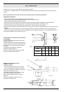
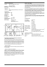
APPENDIX
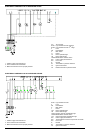
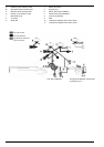
PUMP OPERATING PRINCIPLE
The gear set draws oil from the tank through the built-in filter and transfers it to the nozzle line via the cut off solenoid valve.
Pressure regulation is assured by two spool valves, one for each pressure mode.
In one pipe operation, oil which is not required at the nozzle is returned directly to the gear inlet via the pressure regulating
valves and the suction line flow is equal to the nozzle flow.
In two pipe operation, the by-pass plug must be fitted in the return port, which ensures that the oil dumped by the regulating
valves is returned to the tank and the suction line flow is equal to the gear set capacity.
Purging on 2 pipe installations is assured by a bleed flat on the pistons. On 1 pipe installations, a high pressure connection
must be loosened until the air is evacuated from the system.
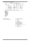
Switching between low and high pressure is assured by a normally open by-pass solenoid valve. When this solenoid is non
activated, a by-pass channel is open, allowing the normal operation of the low pressure valve which sets the nozzle pressure.
When this solenoid is activated, the by-pass channel is closed, thus pressure will build up on both sides of the low pressure
valve eliminating its effect and the high pressure valve now determines the nozzle pressure.
The blocking solenoid valve is of the normally closed type and is situated in the nozzle line.
This design ensures extremely fast response and the switching can be selected according to the burner operating sequence
independently from the motor speed.
When the solenoid is non-activated, the valve is closed and all oil pressurised by the gear set passes through the regulators
to suction or the return line, depending upon the pipe arrangement.
As soon as the solenoid is activated, oil passes to the nozzle line at the pressure set by the pressure regulating valve.