


14
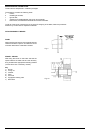
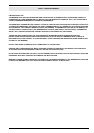
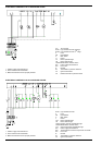
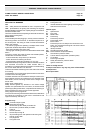
ELECTRICAL DIAGRAM code 01-369 BURNER G18SP
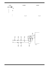
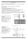
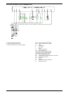
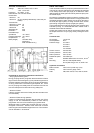
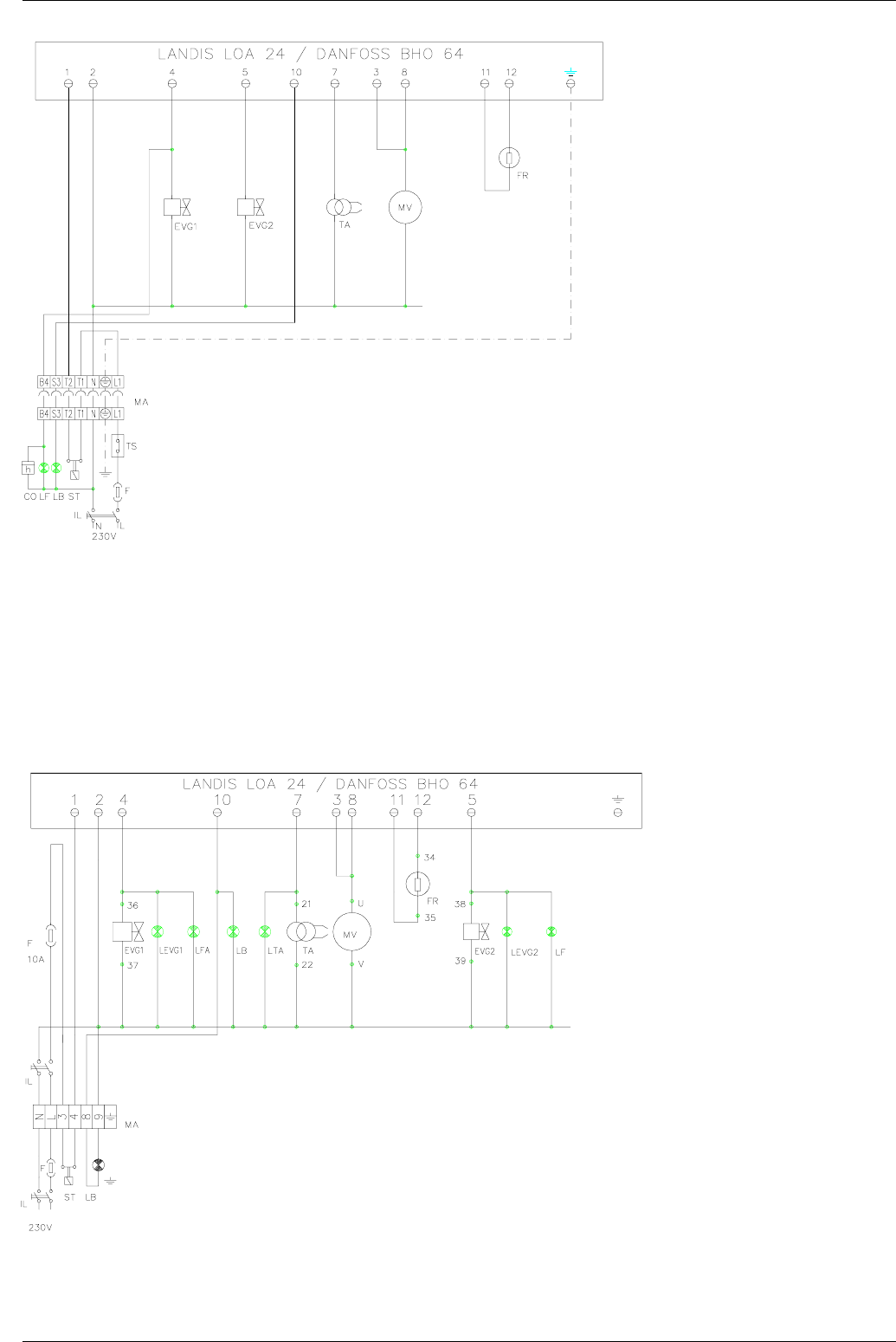
ELECTRICAL DIAGRAM code 04-575 BURNER PG25SP
1 - Electric supply 230V 50Hz 2N a.c.
2 - Don't reverse Phase and Neutral
3 - Make sure that the burner is properly hearted
1 - Electric supply 230V 50Hz 2N a.c.
2 - Don't reverse Phase and Neutral
3 - Make sure that the burner is properly hearted
CO Time counter
EVG1 Light oil solenoid valve I
st
stage
EVG2 Light oil solenoid valve II
nd
stage
F Fuse
FR Photoresistor
IL Main switch
L1 Phase
LF Burner operation light
LB Burner lockout light
LOA24/BOA64 Flame monitor device
MA Power supply terminal block
MV Fan motor
N Neutral
ST Thermostats or pressure switches
TA Ignition transformer
TS Boiler thermostat or pressure switch
EVG1 Light oil solenoid valve
F Fuse
FR Photoresistor
IL Main switch
L Phase
LFA Burner operation light
LB Burner lockout light
LEVG1 Opening of EVG1 signalization light
LOA24/BOA64 Flame monitor device
LTA Ignition transformer signalization light
MA Power supply terminal block
MC Terminal block for burner components connection
MV Fan motor
N Neutral
ST Thermostats or pressure switches
TA Ignition transformer
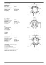
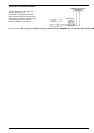
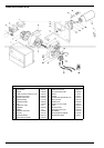
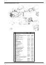
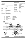
MAINTENANCE