


13
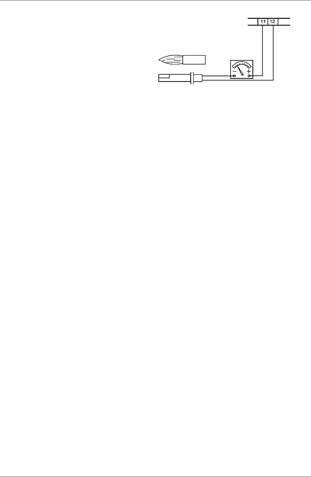
Fig. 14
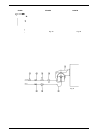
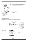
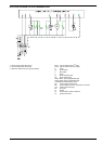
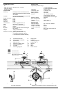
CHECK OF THE IONIZATION CURRENT
To check the detector signal follow the
prcedure shown in fig. 14.
If the signal is not within the prescribed
range, check the electrical contacts; check
also that the combustion head is clean and
the photoelectric sensor is correctly
positioned. Replace it if necessary.
TERMINAL BLOCK MC
Scale µA DC
Minimum current .7067 ( witt )Tj/TT3 1 Tf52.9337 (-0.0101 Tc-0.0061 Tw[flame:)-6187.8(65e µT)]TJ -10 -1523 TD-0.0002 Tc-0.0516 TwMaxnimum current 467067 ( witoutt )Tj/TT3 1 Tf33.5337 (03 Tc0.001 Tw[flame:)-4346.7(5e µT)]TJ -1.084 -1533-3 TD-0.0002 Tc-0.0376 TwMaxnimum(posibale current )Tj/TT2 1 Tf-1.93337 (00.0547067 ( witt )Tj/TT3 1 Tf52.9337 (-0.0006 Tc[flame:)-19606.6200e µT)]TJ/TT5 1 Tf8 0 0 8279.626 24.88 Tm0.0071 TcMAINTENANCE
F
AULA
S FINDING T
ABLET