


19
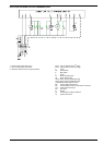
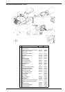
Technical characteristics
Voltage 220V-15%..240V+10% or 100V
-15%...110V+10%
Frequency 50...60Hz +/- 6%
External fuse max.10A slow action
Contact flow:
- terminal 1 5A
- terminal 3 5A (incl.capacity absorbed by motor and pre-
heater)
Terminal flow:
- terminals 4, 5 &10 1A
- terminals 6&7 2A
- terminal 8 5A
Absorbed cap 3VA
Protection IP40
Premitted temp:
operational -20...+60°C
transport & storage -50...+60°C
Emplacement any
Mass (weight) controller 180 g
socket 50 g
AGK accessories 12 g
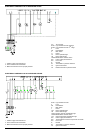
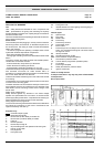
Commands in the event of operational interference
- Stray light/premature ignition
During pre-purge and/or pre-ignition there should be no flame
signal. If there is a flame signal, eg from premature ignition due
to a faulty solenoid, external light, short circuit in the photoresistor
or wiring, malfunction in the flame signal amplifier, etc., at the
end of pre-purge and safety time the controller locks out the
burner and stops the fuel flow even during safety time.
- Absence of flame
If there is no flame at the end of safety time the controller locks
out immediately.
- Absence of flame during operation
If there is no flame during operation the controller cuts off the
supply of fuel and automatically initiates a fresh start-up
programme: at the end of t4 the start-up programme ends.
Whenever there is a safety stop, terminals 3-8 and 11 are de-
energised in less than 1 second; at the same time a remote
lockout signal is transmitted through terminal 10. The controller
can be reset after c. 50 seconds.
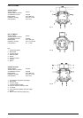
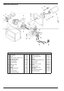
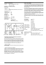
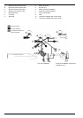
DELTA “VM” PUMPS
In the VM series of DELTA pumps the pressurised flow of oil P
is shut off by a built in solenoid and may therefore be switched
on for startup of the motor pre-purge) or off before the motor
itself switches off (flame goes out instantly when the spray from
the nozzle stops).
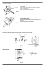
Oil pressure is regulated and kept constant by the piston valve
which is activated when the light comes on to signify that the oil
discharged exceeds nozzle capacity and is being returned to
the tank (twin-pipe system) or being returned to the suction
pipe through a bypass in the pipe (single-pipe system).
In this model both the single-pipe and twin-pipe versions have
automatic priming. It is recommended that in eiether case a
standard external filter be installed.
All twin-pipe models can be used as single-pipe systems with
the simple removal of a nylon plug and by closing the return
pipe.
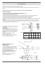
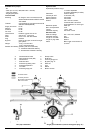
Technical data
Oil viscosity 1,5÷50 cSt
Oil temperature 50°C
Pressure range 2÷10 bars
4÷15 bars
8÷20 bars
10÷125 bars
Suction vacuum max.0,5 bars
Suction pressure max.0,7 bars
Return pressure max.1,5 bars
Rotational speed max.3500 rpm
Filter stainless steel mesh 110 micron, 20 cm
2
Mounting Hub 32, shaft 8 (DIN 24220)
On request: flange, hub 54, shaft 7/16"
Hydraulic connections
Return suction 1/8"G 1/4"G (1/8"G only Vl,V2)
Delivery 1/8"G vacuum gauge 1/8"G
Rate VMl, VM2: max.0,1 Nm; VM3: 0,18 Nm
APPENDIX