


18
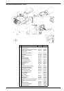
APPENDIX: COMPONENTS CHARACTERISTICS
FLAME CONTROL DEVICE LANDIS LOA24 Page 18
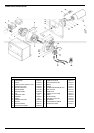
LIGHT OIL PUMPS Page 19
LANDIS AUTOMATIC CONTROLLER LOA24
FOR LIGHT OIL BURNERS
Use
LOA... safety devices are intended for use in conjunction with
QRB... photoresistors, for lighting and controlling low capacity
forced air diesel burners with max. capacity 30 kg/h in accordance
with standard DIN 4787.
The One or two flames are lit, depending on electrical connections,
with or without post-ignition.
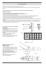
Performance
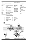
The controllers just need plugging in, so they can be mounted in
almost any position: on the burner, on the electrical panel or on
the control panel. The casing is made of robust heat-resistant
plastic and contains:
- the thermic programmer operating a multiple switch control
system with ambient temperature compensator
- flame signal amplifier with flame relay
- warning light indicating lockout and associated sealed reset
button.
The plug-in socket, also made of robust heat-resistant plastic,
contains the 12 terminals and also:
- 3 neutral terminals, ready wired up to terminal 2
- 4 earth terminals for earthing the burner
- 2 supplementary terminals numbered “31” and “32”.
The socket has two openings at the bottom for the leads; 5 others
with threaded connection for cable holders PG11 or
3/4UNP for non-metallic sleeves are located on a mobile stuffing
box, one on either side and 3 on the front.
There are two flexible metal tongues on the sides of the socket
for mounting.
To dismantle it only requires gentle pressure with a screw driver
in the slot of the mounting guide.
The base dimensions of the socket are exaclty the same as for
types LAB/LAI and there is no difference in the diameter of the
reset button, the two mounting screws and the flange of the
burner earth.
Safety at low voltage levels
Safety devices against any reduction in the mains voltage
operate on a special electronic circuit which, in the event of the
power supply falling below 165V~, stops the burner switching on
without releasing the fuel and locks out the apparatus.
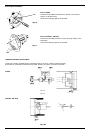
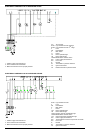
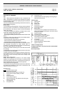
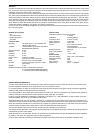
Wiring diagram of the programme
To ensure correct wiring it is essential to observe local standards
and follow the instructions of the burner manufacturer with
regard to assembly and start-up.
Program's key:
Controller output signals
Required input signals
A’ Burner start up with diesel pre-heater OH
A Burner start-up without diesel pre-heater
B Flame lit
C Normal operation
D Normal stop through R
tw Oil pre-heating time until operational all clear given
through contact OW
tl Pre-purge time
t3 Pre-ignition time
t2 Safety time
t3n Post-ignition time
t4 Interval between the flame lighting and energising of
solenoid 2a at terminal 5
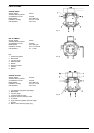
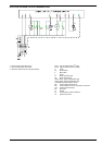
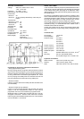
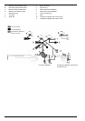
Internal layout
AL Optical alarm
BV. Fuel valve
EK Reset button
FR Flame relay
fr Flame relay contacts
FS Flame alight signal
G Burner motor
K Flame relay anchor to delay the tzl command in the
event of a premature flame signal or endorse it where
the signal is correct.
OH diesel pre-heater
OW Operational all-clear contact
QRB Photo-resistant cell (flame detector)
R Thermostat or pressure switch
TZ Thermo-electric programmer (bimetal system)
tz.. TZ contacts
V Flame signal amplifier
W Safety thermostat or pressure switch
Z Ignition transformer
These are safety devices
To tamper with them in any way may have unforeseeable
consequences !
Do not open them!
APPENDIX