


12
C
AR
VRT
R
C
V
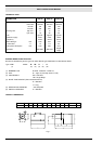
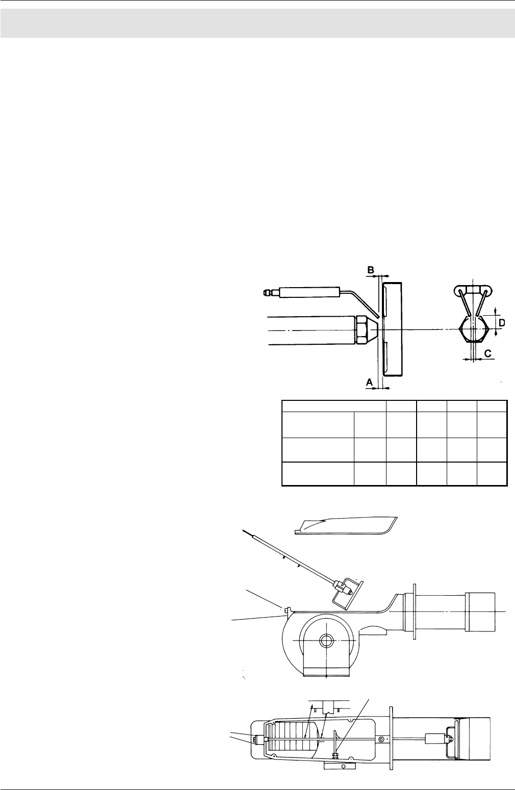
Fig. 13
Fig. 13a
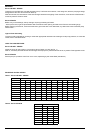
ABCD
60°6446
45°10546
60°8446
45°12546
60°8446
45°12546
G18 SP
PG28SP
PG30TN
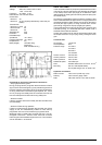
PART III: MAINTENANCE
At least once a year carry out the following maintenance procedures.
If servicing is on a seasonal basis, it is recommended at the end of the season; routine sevice should be carried out every
months.
Note: Any operation on the burner must be carried out with the main electricity switched off.
PERIODICAL SERVICING
- Clean and examine the oil filter cartridge and replace it if necessary;
- Examine the condition of the oil flexìble pipeworks and check for possible leaks;
- Clean and examine the filter inside the oil pump;
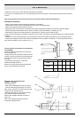
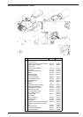
- Dismantle, examine and clean the combustion head. When reassembling respect the measures reported in table 3.
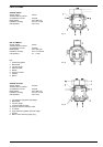
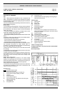
- Examine the ignition electrodes and their ceramic insulators, adjust and replace if necessary (fig. 13);
- Dismantle and clean the oil nozzle (important: use solvents for cleaning and not metal utensils).
At the end of the maintenence procedures replace the burner, light it and check the shape of the flame:if in doubt replace the
nozzle(s);
where the burner is used intensively it is recommended to replace the nozzles at the beginning of the operating season;
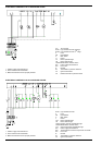
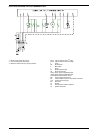
- Examine and carefully clean the flame detector photoelectric cell and replace if necessary. If in doubt light the burner and
then check the detector circuit as shown in Fig. 14.
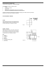
Correct position of electrodes and combustion
head (G18SP)
Prepare a stable surface where lying the burner
during maintenance.
To gain access to the combustion head and to the
nozzles, loose the screw which lock the blast tube
and remove it from the part that remains fixed to
the boiler.
To guarantee a good ignition, respect the
measures indicated in table 3.
Be sure to lock the screw that fix the electrodes
group, before reassembly the burner.
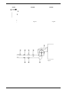
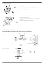
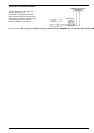
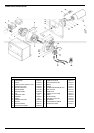
Removal of the combustion head
(PG25SP - PG30TN)
- Remove the cap C;
- Take out the photoresistance from its housing;
- Unscrew the floating pipe-fitting E from the oil
pipe, using 2 spanners, to avoid to loose the pipe-
firrings from the distribution block;
- Remove the screws V and unscrew the screw
VRT until the threaded rod AR is free;
Remove the complete assembly as shown in
figure 13a.
Note: To re-assemble reverse the order of
procedures descibed above.
MAINTENANCE
Table 3