


10
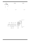
VBS
VBS
+
-
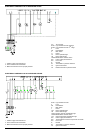
Fig. 12
Fig. 11
Fig. 10
Fig. 12a
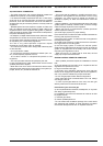
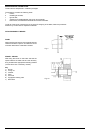
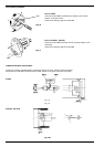
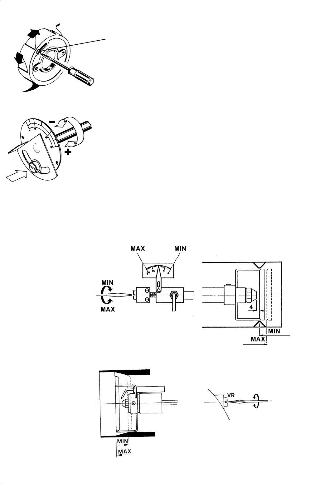
AIR FLOW ADJUSTMENT
Burner G18SP
Loose the screw VBS and rotate the air damper in the desired
position, to set the air flow.
At the end of settings, tight the screw VBS.
Burners PG25SP - PG30TN
Loose the screw VBS and set the air flow, working directly on the
air damper.
At the end of settings, tight the screw VBS.
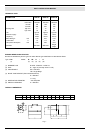
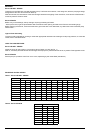
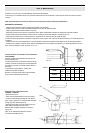
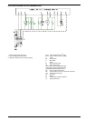
COMBUSTION HEAD ADJUSTMENT
The burner is factory-adjusted with the combustion head in the “max” position (maximum output).
Move back the combustion head towards the “MIN” position, turning the screw VRT clockwise.
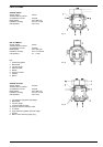
PG25SP - PG 30TN
G18SP
Fig. 12
Fig. 11
Fig. 10
Fig. 12a
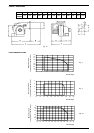
INSTALLATION