


Installation Instructions CM2L40
9
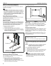
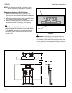
NOTE: Verify that there is at least 1" of clearance between
bottom of display and mount base.
3. If there is less than 1" of clearance, remove the display and
refer to Adjusting Faceplate Location section, and adjust
display height accordingly.
NOTE: Holes are provided in the faceplate for use with a
padlock or similar locking device, if desired. In addition,
the pin and nut may be removed from the upper holes
and moved to the lower holes for use as a more
permanent locking device. (See Figure 10)
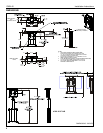
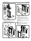
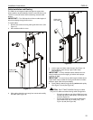
Shelf Height Adjustment
After the CM2 has been properly configured for the display and
the display installed, the shelf height needs to be adjusted to
the top of the display.
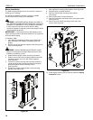
To set shelf height:
1. Using the remote control, raise lift until locknuts securing
right and left shelf adjustment brackets can be accessed.
Figure 11
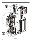
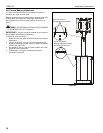
2. Loosen four nuts securing right and left hand shelf
adjustment brackets to faceplate mounting bracket.
3. Slide shelf adjustment brackets upward until top of brackets
are positioned higher than top of display. (See Figure 12)
Figure 12
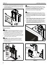
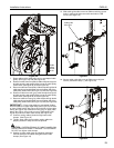
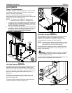
4. Re-install shelf assembly to shelf adjustment brackets by
aligning studs in shelf bracket with clips in shelf adjustment
brackets.
Figure 13
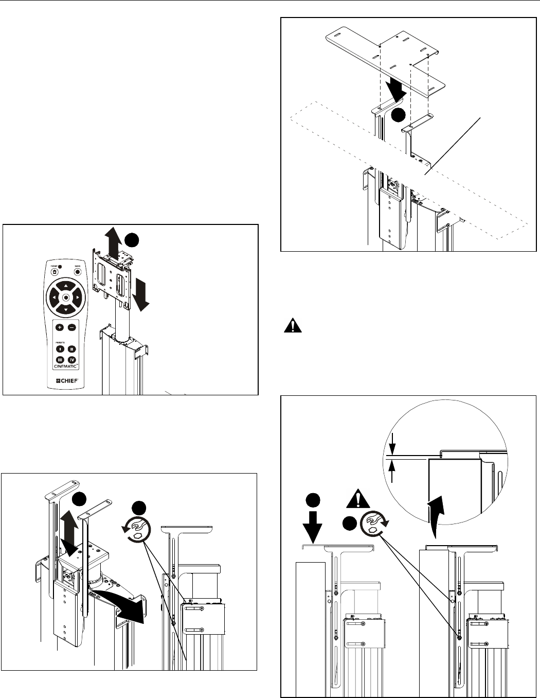
5. Lower shelf and shelf mounting brackets down until shelf is
1/4" (6.5mm) above top of display.
6. Tighten four nuts to secure shelf mounting bracket in
position.
WARNING: IMPROPER INSTALLATION CAN LEAD TO
SEVERE PERSONAL INJURY OR DAMAGE TO
EQUIPMENT! Make sure all four nuts are tight before
continuing installation!
Figure 14
1
Display removed
for clarity
Display and Faceplate
removed for clarity
3
2
X4
5
Top of Display
6
x 4
5
1/4" (6.5mm) min.