


CM2L40 Installation Instructions
6
INSTALLATION REQUIREMENTS
The CM2 has been designed to be mounted into a cabinet or
similar type of furnishing.
WARNING: IMPROPER INSTALLATION CAN LEAD TO
LIFT TIPPING CAUSING SEVERE PERSONAL INJURY OR
DAMAGE TO EQUIPMENT! It is the installers responsibility
to make certain the structure to which the lift is being
mounted is capable of supporting 4 times the weight of the lift
and all attached equipment.
Power Requirements and Wiring
The CM2 requires 120VAC (220/240VAC 50 Hz for European
installations) power to operate.
A 6 ft long power cable is provided with the mount.
INSTALLATION
Pre-Installation Configuration and Adjustments
Prior to being installed, the CM2 requires the configuration of
the mount for display, cable installation and routing, and the
rough adjustment of the top cover mounting bracket.
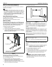
To prepare the CM2 for Installation:
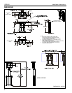
1. Remove mount from box.
2. Remove two wooden supports from under box.
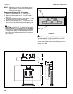
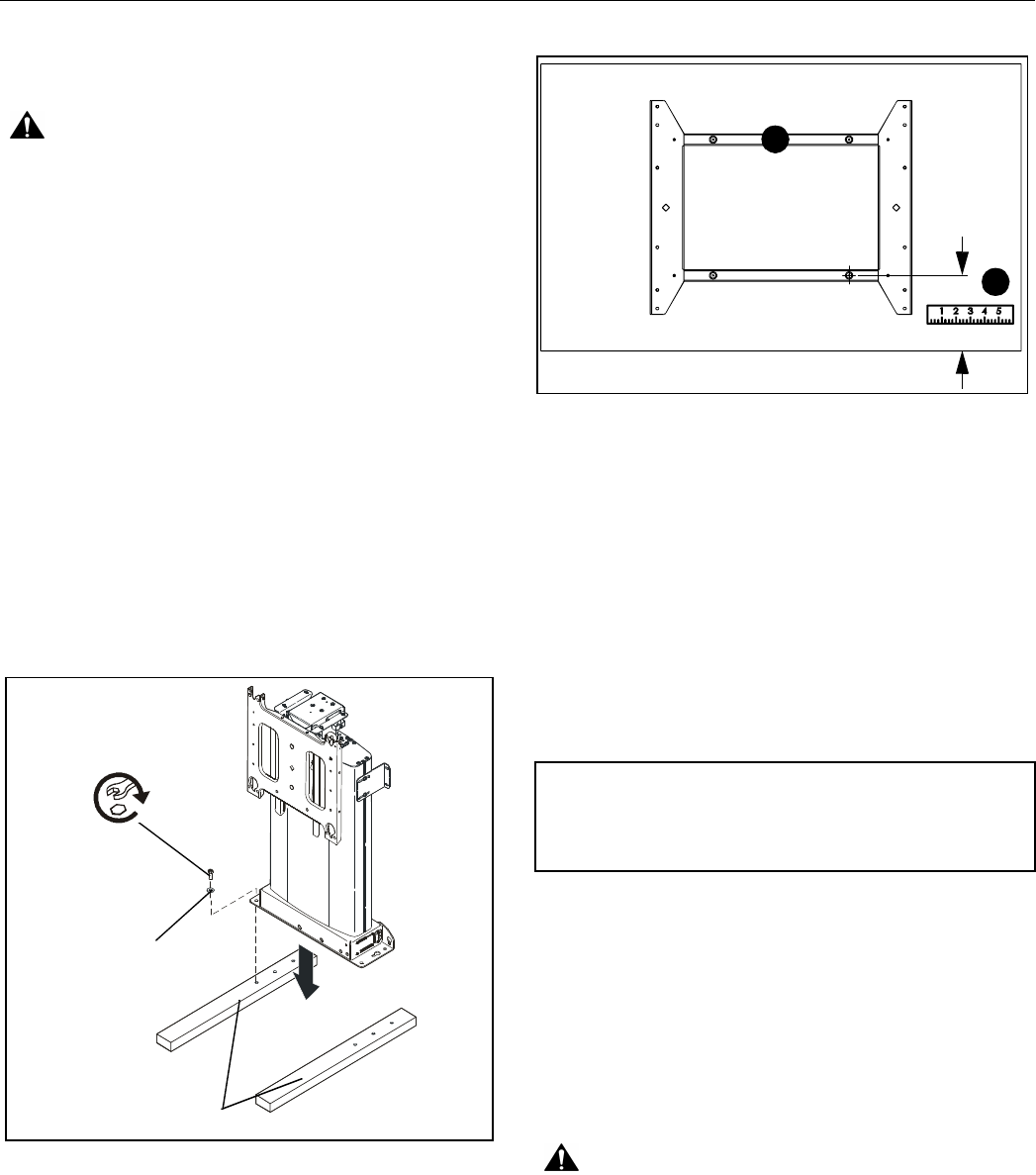
3. Lay two wooden supports on floor and mount to supports
using four 5/16" flat washers and four 5/16" x 2 1/2" lag bolts
(hardware provided). (See Figure 1)
Figure 1
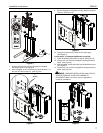
Configuring the Mount for the Display
Prior to installation, the CM2 needs to be configured for the
size of the display being used.
To prepare the CM2 for the display being installed:
1. Install interface bracket or mounting buttons to display
following the instructions provided with bracket.
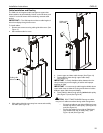
2. Measure the distance from the center of a bottom mounting
button to the lowest point of the display.
3. Record measurement.
Figure 2
IMPORTANT ! : If the dimension taken in Figure 2 is greater
than 16" (406mm), the faceplate will need to be adjusted
before mounting the display. If the dimension taken in Figure 2
is less than 16" (406mm) proceed to Display Installation
section.
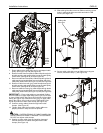
Adjusting Faceplate Location
The CM2 is designed to allow up to 6.5" of adjustment. Up to 2"
by adjusting the faceplate location on the faceplate mounting
bracket, and up to an additional 4.5" by adjusting the faceplate
mounting bracket.
Subtract 16" from the dimension determined in Figure 2. The
difference between the two is the total amount of adjustment
the faceplate will require.
If 2" or less faceplate adjustment is required proceed to Step 5.
If more than 2" of faceplate adjustment is required proceed to
Step 8.
NOTE: Depending upon the amount of faceplate adjustment
required, it may be necessary to adjust both the
faceplate and faceplate mounting bracket.
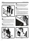
If 2" or less faceplate adjustment is required:
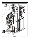
4. Install IR receiver. (See Figure 3)
5. Plug appropriate power cord into mount and power source.
6. Using the remote control, raise lift until locknuts on back
side of faceplate can be accessed. (See Figure 3)
WARNING: PINCH HAZARD! FINGERS OR HANDS
BETWEEN MOVING PARTS CAN LEAD TO SEVERE
PERSONAL INJURY! Keep fingers and hands away from
mount when operating.
Lag Bolt
Flat Washer
Wooden Supports
(from bottom of box)
2
1
Example:
Dimension from Step 2 = 19.5"
19.5" - 16" = 3.5" (Amount of faceplate adjustment required)