


Page 21
J500
H2
100A
UD
H2
100A
UD
3D2
100
16B
J406 LCD
J201
MIC
J403
D2
D102
D153
3D2
100
16B
3D2
100
16B
3D2
100
16B
H2
100A
UD
3D2
100
16B
J400
+
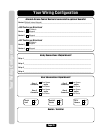
DEVICE 1,2
DescriptionType
Used on Model
1
11
10
9
8
7
6
5
4
3
2
No.
Board
Label
EL25 EL2000
Name
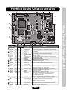
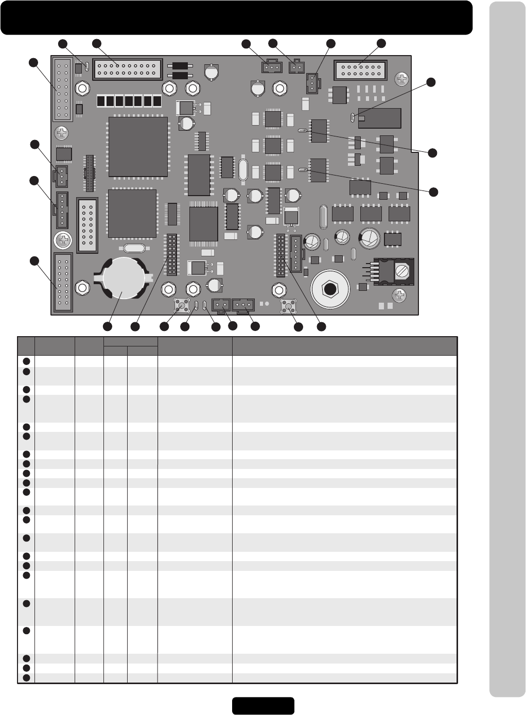
LED D300 X X PWR LED Indicates Unit is receiving power
Connector J405 X X 20-Pin Connector Connector to IO Input Board. The IO Input Board contains all REX inputs,
to IO Input Board DSC inputs and Postal input, Auto Sensor input and Power. Provides power
Connector J500 X LCD PWR to LCD Display.
Connector J406 X X EL25=LED BOTTOM For the EL25 provides power to bottom lighted LEDs for the main keypad.
KEYPAD On the EL2000 this is the top lighted LEDs for main keypad.
EL2000=LED keypad
Connector J201 X X MIC Microphone connector
Connector J403 X X 14-Pin Connector to Connector to the Output Board. The Output Board contains the Resident,
Output Board Telco and dry contact Relays.
Connector J401 X X KEYPAD Connector for the main keypad
LED D2 X X Local Mode Unit supplying Central Office Power to Resident
LED D102 X X RES DAA OFF HOOK Resident side of circuit is off hook
LED D153 X X TELCO DAA OFF HOOK Telco side of circuit is off hook
Connector J301 X X Direct Connect Used for direct connect and handheld programming and Real
(Serial Port) Time Monitoring.
Connector J404 X X LED Power Supply
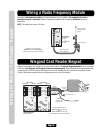
Connector J407 X X Module Device (3,4) Connect a module (Wiegand or RF) device here. The device address
becomes 3 (RF or Wiegand-J1) or 4 (Wiegand-J2)
Connector J400 X X Module Device (1,2) Connect a module (Wiegand or RF) device here. The device address
becomes 1 (RF or Wiegand-J1) or 2 (Wiegand-J2)
Connector J300 X LCD Data Data wires for LCD Display
Connector BT300 X X Battery Battery used to back-up the Unit’s real time clock.
Switch SW300 X X OV/UV Reset Switch to turn off OV/UV LEDs. This button will turn off the OV/UV
LEDs momentarily. If a poor power condition still exists then the
OV or UV LEDs may turn on again.
LED D513 X X Over-Voltage (OV) Over-Voltage LED. Turns on when the Unit detects an over voltage
of 16.5 VAC or 22.3 VDC at power block J1. Measure the voltage at
power block J1 to confirm.
LED D514 X X Under-Voltage (UV) Under-Voltage LED. Turns on when the Unit detects an under
voltage of 9.5 VAC or 10.2 VDC at power block J1. Measure the
voltage at power block J1 to confirm.
Connector J402 X LED TOP KEYPAD For the EL25, provides power to the top lighted LEDs for main keypad.
Connector J200 X X Main Speaker Main Speaker
Switch SW500 X X Soft Reboot Reboots firmware without removing power.
13
12
14
17
16
15
18
19
21
20
J407
J401
D300
D513
D514
OV
UV
J404
J402 LEDJ200 SPKR
J300
BT300
DEVICE 3,4
SW300
J405
J301
1
2
3
4
5
6
8
9
10
14
21
20
19
18
17
13
16
15
7
11
12
22
22
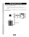
Powering Up and Checking the LEDs
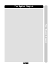
Wiring Power and Powering Up Unit