


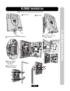
Page 9
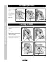
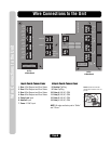
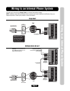
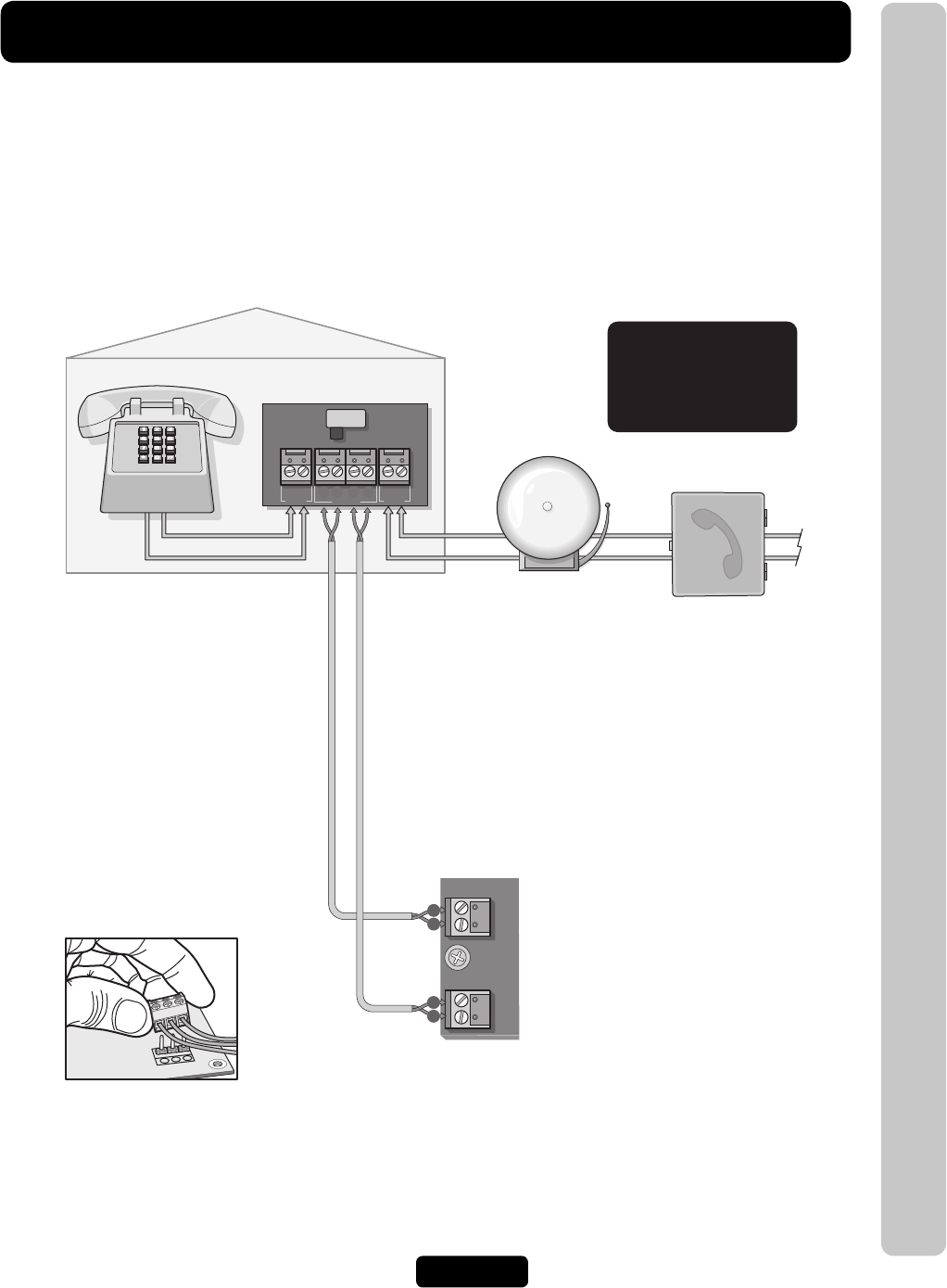
Wiring 1 Unit to Telco Line
Wiring 1 Unit to Telco Line
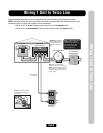
The bypass board allows the unit to be disconnected without interrupting normal telephone operation.
NOTE: Installation where fiber optic phone lines are present may require additional modifications from your
telephone provider. Contact your provider for more information.
• When the unit is in use, the bypass switch must be set to the operate position.
• When the unit is disconnected, the bypass switch must be set to the bypass position.
Tip
Ring
Tip
Ring
OPERATE BYPASS
Ring
HOME
Tip Ring
TELCO
Tip
SYSTEM
Bypass Board
(Mount in the House)
(NOT Provided)
Ring
Tip Ring
Tip
Home Phone
Alarm System Position
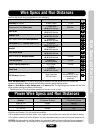
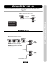
Use 18-24 AWG
2 twisted pair
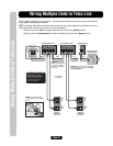
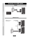
NOTE: If the unit will be used in
conjunction with an alarm system, you
MUST connect the telephone line to the
alarm system first. If the units are not
connected in this order, they will not
operate properly.
4
4 3 2 1
3
2
1
Output Board
(See page 6)
Telco Entrance Box
Demarcation Point
DO NOT overload the removable
terminal block connectors. One
wire per hole.
IMPORTANT: The Bypass
Board (located inside the
property) allows access to
the phone in case the unit
fails.
Never run Telco wires and High
Voltage wires in the same
conduit. The high voltage wires
may interfere with the Telco
wires, possibly causing the
system to malfunction.
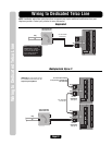
RES
TELCO