


Page 18
Wiring a RF Module / Card Reader / Keypad
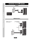
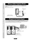
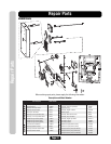
Wiring a Radio Frequency Module
An optional radio frequency module and a remote antenna can be installed if the residents will access a
controlled area with a transmitter. Refer to instructions supplied with the optional RF Module for more
information.
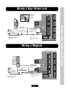
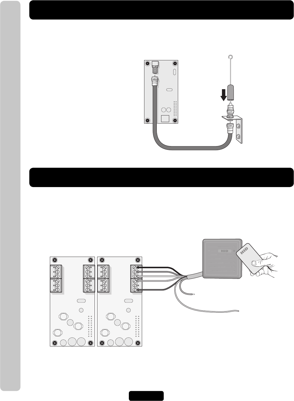
Wiegand Card Reader/Keypad
Wiegand card readers and keypads can be connected to either of 2 optional Wiegand modules that can be placed
in the unit. Each Wiegand module supports two card readers/keypads. Some Wiegand card reader/keypads have
a sixth blue wire. DO NOT connect this blue wire to the unit. Insulate this wire from the unit to prevent a short
(Refer to instructions supplied with your Wiegand device for more information).
RG-6
Coaxial
Connector
RG-6 Coaxial Cable
100 Feet Maximum
Remote Antenna
Avoid any metallic
surface around the
antenna.
RF Module(s) will fit in positions
J400 (Device 1) and/or J407 (Device 3)
(4 Mounting Screws per Board are Required)
1 RF Module Kit
Part # RFMODKT
(390 MHz)
or
Part # RFMODKT3
(315 MHz)
J407 Position J400 Position
Card Reader is Wired to Device 1
P12V
P5V
DATA 0
DATA 1
LED
COM P12V
P5V
DATA 0
DATA 1
LED
COM
J1J2 J1J2
Device 1Device 3 Device 2Device 4
Red Power
Green
White
Brown
Black
Shield
(Attach to the
unit ground only).
Blue (Insulate this wire).
Use 18-24
AWG
1 Wiegand Module Kit
Part # WOMODKT
P12V
P5V
DATA 0
DATA 1
LED
COM P12V
P5V
DATA 0
DATA 1
LED
COM
Wiegand Modules will fit in
J400 as Device 1 (J1) and 2 (J2)
and/or
J407 as Device 3 (J1) and 4 (J2)
(4 Mounting Screws per Board are Required)
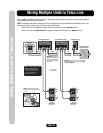
NOTE: The remote can control 1-4 doors.