


Page 14
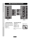
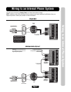
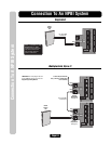
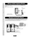
Connection To A NPBI System
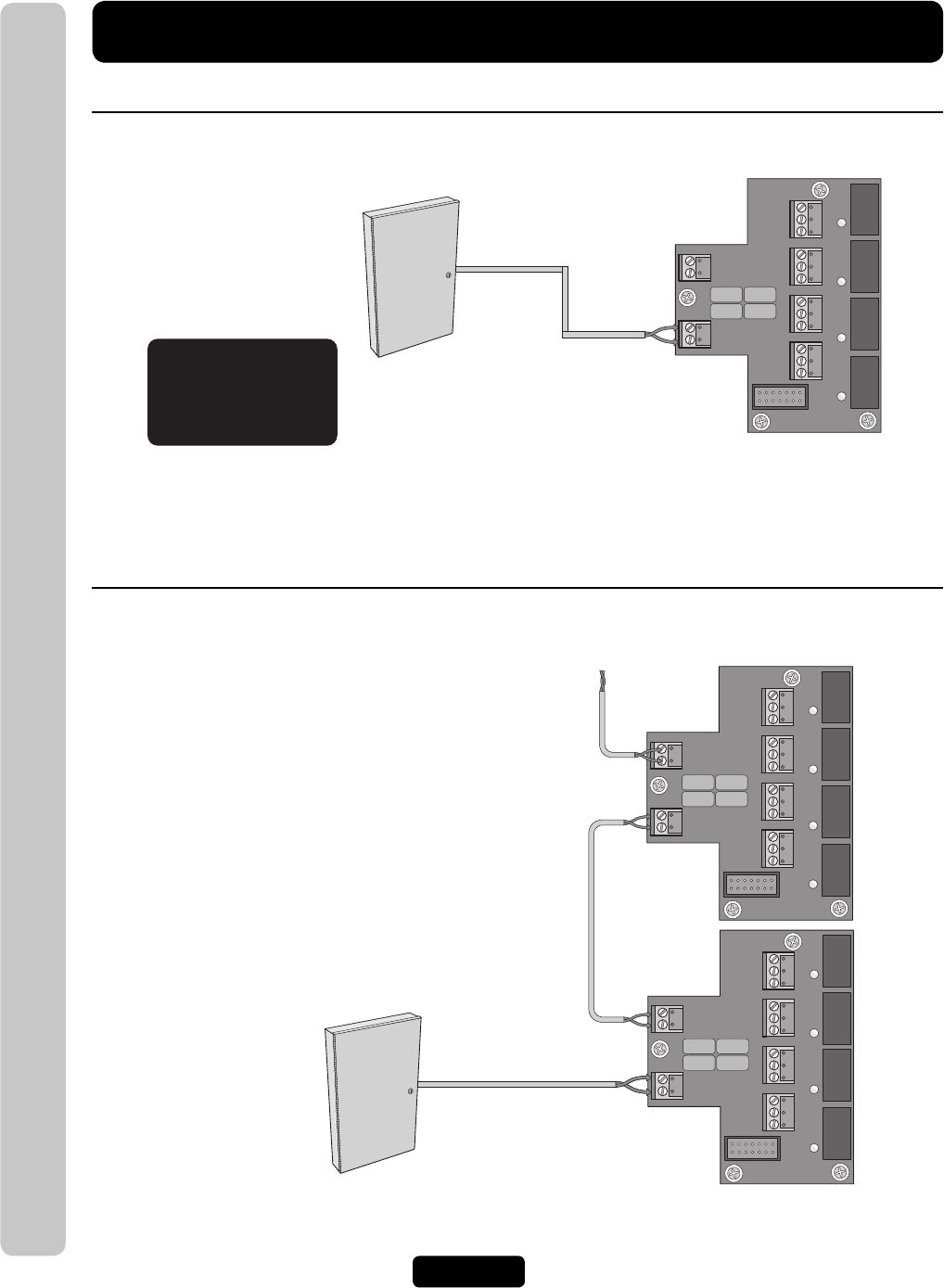
Connection To An NPBI System
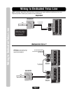
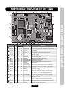
IO Output Board
LED 2
LED 1
RELAY 1
RELAY 2
RELAY 3
RELAY 4
J3
J5
J4
J1
NO
NC
C
NO
NC
C
NO
NC
C
NO
NC
C
LED 4
LED 3
RES
TELCO
J6
J8
Tip
Ring
Tip
Ring
IO Output Board
LED 2
LED 1
RELAY 1
RELAY 2
RELAY 3
RELAY 4
J3
J5
J4
J1
NO
NC
C
NO
NC
C
NO
NC
C
NO
NC
C
LED 4
LED 3
RES
TELCO
J6
J8
Tip
Ring
Tip
Ring
IO Output Board
LED 2
LED 1
RELAY 1
RELAY 2
RELAY 3
RELAY 4
J3
J5
J4
J1
NO
NC
C
NO
NC
C
NO
NC
C
NO
NC
C
LED 4
LED 3
RES
TELCO
J6
J8
Tip
Ring
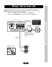
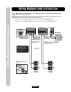
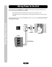
Never run Telco wires and High
Voltage wires in the same
conduit. The high voltage wires
may interfere with the Telco
wires, possibly causing the
system to malfunction.
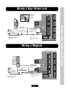
Use 18-24 AWG
2 twisted pair
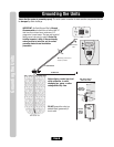
IMPORTANT: You must program the Unit
ID's for each unit wired in the series. See
Keypad Programming Manual.
Unit ID 6
Output Board
(See page 6)
Unit ID 7
Output Board
(See page 6)
Use 18-24 AWG
2 twisted pair
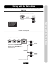
Sentex
Ovation
Unit
To next unit (Unit ID 5 then
4 etc.) Unit ID 1 is farthest away
from Telco Box)
Sentex
Ovation
Unit
Single Unit
Multiple Units (Up to 7)