


Page 15
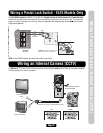
Wiring a Door Strike Lock/Maglock
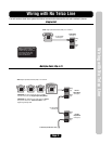
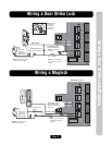
Wiring a Door Strike Lock
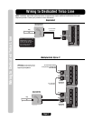
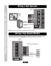
Wiring a Maglock
IO Output Board
LED 2
LED 1
RELAY 1
RELAY 2
RELAY 3
RELAY 4
J3
J5
J4
J1
NO
NC
C
NO
NC
C
NO
NC
C
NO
NC
C
LED 4
LED 3
RES
TELCO
J6
J8
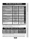
Use 18-22 AWG
NOTE: The door strike can
be connected to any of the
4 relays.
Normally Open
Common
DO NOT use the unit’s power
supply for the Door Strike.
–
+
AC or DC
Power for
Door Strike
(Not Provided)
DO NOT overload
the removable
terminal block
connectors. One
wire per hole.
Output Board (See page 6)
For DC Power: Install a
1N4005 diode or equivalent.
For AC Power: Install a
Siemens S10K30 MOV
(Metal Oxide Varistor) or
equivalent.
IO Output Board
LED 2
LED 1
RELAY 1
RELAY 2
RELAY 3
RELAY 4
J3
J5
J4
J1
NO
NC
C
NO
NC
C
NO
NC
C
NO
NC
C
LED 4
LED 3
RES
TELCO
J6
J8
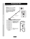
Output Board (See page 6)
Install a 1N4005 diode or
equivalent.
NOTE: The maglock can be
connected to any of the
4 Relays.
DO NOT use the unit’s power
supply for the Maglock.
Use 18-22 AWG
–
+
Normally Closed
Common
AC or DC
Power for
Door Strike
(Not Provided)
For AC Power: Install a
Siemens S10K30 MOV
(Metal Oxide Varistor) or
equivalent.