


Page 3
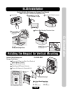
EL25 Installation
EL25 Installation
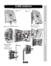
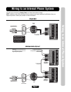
DO NOT overload the removable
terminal block connectors.
One wire per hole.
DO NOT pinch wires when
closing and locking the unit.
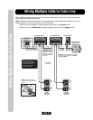
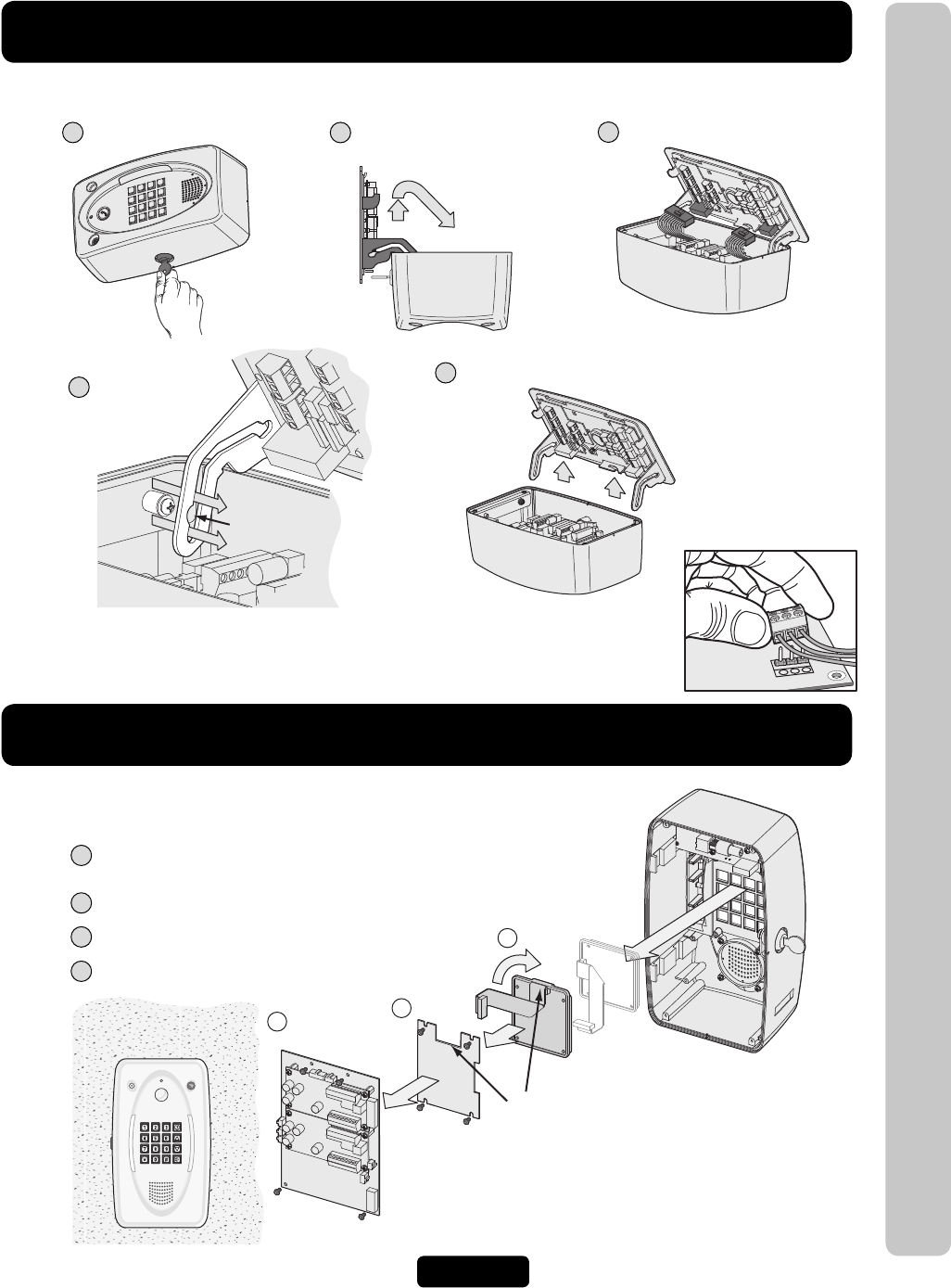
Rotating the Keypad for Vertical Mounting
Screw
Notch
1
2
3
Bracket
Keypad
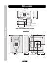
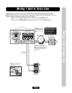
Main Circuit
Board
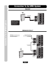
Main Circuit Board Connections
J200 - Speaker
J402 - Light
J404 - Call Button Board
ONLY Vertical
Mounting Position
J401 - Keypad
J406 - Light
J201 - Microphone
NOTE: Bracket notch lines up
with ribbon cable on keypad.
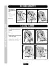
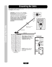
Caution! A Static Discharge can
Damage Circuit Boards
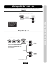
For EL25 ONLY
Caution! A Static Discharge can Damage Circuit Boards
1
Unlock Unit
2
Carefully Lift Cover Up
then Slide Out on Hinges
3
Unplug the 2 Main Harnesses
4
Line up Notch with
Screw and Push
Hinge Out
5
Remove Back Mounting Plate from Cover
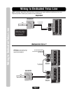
1
Disconnect all Plugs from Main Circuit Board and
Remove Board. (4 Screws)
2
Remove Bracket. (4 Screws)
3
Rotate Keypad 90 Degrees Clockwise.
4
Reverse the Sequence to Reassemble Unit.
NOTE: This unit is for surface mount applications only.