


Adjustment Step 1
Adjust the UP and DOWN Limits
Do not make any limit adjustments until the safety
reversing sensors are completely installed.
24
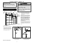
Limit adjustment settings regulate the points at which the
door will stop when moving up or down.
The door will stop in the up direction if anything
interferes with door travel. The door will reverse in the
down direction if anything interferes with the door travel
(including binding or unbalanced doors).
To operate the opener, press the Door Control push bar or
button. Run the opener through a complete travel cycle.
• Does the door open and close completely?
• Does the door stay closed and not reverse
unintentionally when fully closed?
If your door passes both of these tests, no limit
adjustments are necessary unless the reversing test fails
(see page 26).
Adjustment procedures are outlined below. Run the
opener through a complete travel cycle after each
adjustment.
Repeated operation of the opener during adjustment
procedures may cause the motor to overheat and shut off.
Simply wait 15 minutes and try again.
Read the procedures carefully before proceeding to
Adjustment Step 2. Use a screwdriver to make limit
adjustments.
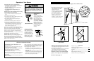
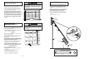
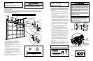
How and When to Adjust the Limits
If the door does not open completely but opens at least
five feet:
Increase up travel. Turn the UP limit adjustment screw
clockwise. One turn equals 2" of travel.
If door does not open at least 5 feet: Adjust the UP
(open) force as explained in Adjustment Step 2.
If the door does not close completely:
Increase down travel. Turn the DOWN limit adjustment
screw counterclockwise. One turn equals 2" of travel.
If door still won't close completely, try lengthening the
door arm. (Page 22.)
If you have adjusted the door arm to the maximum length
and the door still will not close completely, lower the
header bracket. See Installation Step 1, pages 8/9.
If the opener reverses in fully closed position:
Decrease down travel. Turn the DOWN limit adjustment
screw clockwise. One turn equals 2" of travel.
If the door reverses when closing and there is no
visible interference to travel cycle:
If the opener lights are flashing, the Safety Reversing
Sensors are either not installed, misaligned, or obstructed.
See Troubleshooting, page 18.
Test the door for binding: Pull the manual release handle.
Manually open and close the door. If the door is binding,
call for garage door service. If the door is not binding or
unbalanced, adjust the DOWN (close) force. See
Adjustment Step 2.
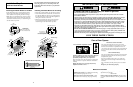
Adjustment Section: Pages 24 – 26
Improper adjustment of the travel limits will interfere with
the proper operation of the safety reverse system. The
door might not reverse properly when required and could
seriously injure or kill someone under it. Test the safety
reverse system monthly, and following all adjustments to
the travel limits. See page 26.
Travel Limit
Adjustment
Screws
LIMIT ADJUSTMENT
LABEL
+
+
Right Side Panel
Adjust UP Travel
Adjust DOWN Travel
+
+
321
Kg
Kg
1
3
8
7
5
1
3
8
7
5
WARNING
CAUTION
WARNING
1/4 x 1-1/2"
Lag Screw
#10 - 32 x 3/8"
Screw
1/4" - 20
Lock Nut
#10 x 32
Lock Nut
Staples
1/4" - 20 x 1/2"
Carriage Bolts
Installation Step 4
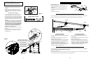
Install the Safety Reversing Sensor
(Receiving and Sending Eyes)
Mounting Bracket
With Square Holes
#10-32x3/8"
Screws
"C" Wrap
#10 - 32
Lock Nuts
Mounting Bracket
with Slot
1/4" - 20
Lock Nuts
1/4 x 1-1/2"
Lag Screws
1/4-20 x 1/2" Carriage Bolts
(with square shoulder)
Inside
Garage
Wall
"C" Wrap
Mounting Bracket
with Square Holes
Inside
Garage
Wall
"C" Shaped
Wrap
Mounting Bracket
with Square Holes
1/4-20 x 1/2"
Carriage Bolts
1/4 " Lock Nuts
Drill 3/8"
Holes
Garage
Door Track
Garage DOOR Track Installation
Garage WALL or DOOR TRACK Installation
Garage WALL Installation
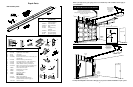
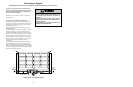
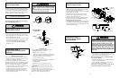
Figures 1, 2 and 3 show recommended assembly of
bracket(s) and "C" wrap based on the wall installation of
the sensors on each side of the garage door as shown on
page 12, or on the garage door tracks themselves.
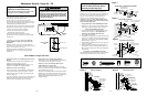
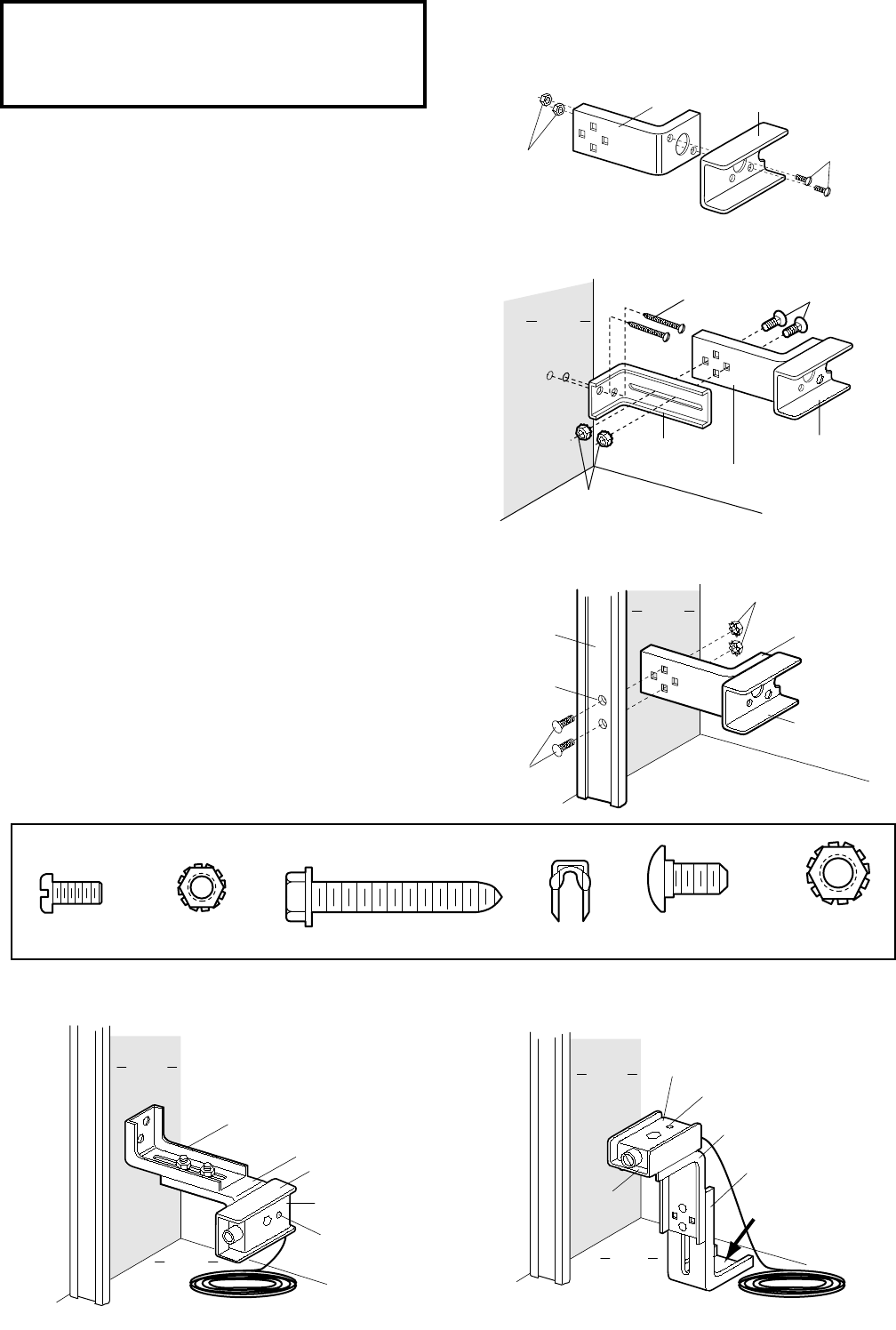
Figures 4 and 5 are variations which may fit your
installation requirements better. Make sure the wraps
and brackets are aligned so the sensors will face each
other across the garage door.
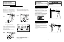
Garage Wall or Door Track Installation Procedure
1. Fasten the "C" wraps to the mounting brackets having
square holes, using the hardware shown in Figure 1.
Garage Wall Installation Procedure
2. Connect each assembly to a slotted bracket, using the
hardware shown in Figure 2. Note alignment of
brackets for left and right sides of the door.
3. Finger tighten the lock nuts.
4. Use bracket mounting holes as a template to locate and
drill (2) 3/16" diameter pilot holes on both sides of the
garage door, 4"-6" above the floor but not exceeding
6" (see warning on page 12).
5. Attach bracket assemblies with 1/4"x1-1/2" lag screws
as shown in Figure 2.
6. Adjust right and left side bracket assemblies to the
same distance out from mounting surface. Make sure
all door hardware obstructions are cleared. Tighten the
nuts securely.
Garage Door Track Installation Procedure
Discard slotted bracket. Drill 3/8" holes in each track and
fasten securely with hardware as shown in Figure 3.
"C" Wrap
Inside
Garage
Wall
Mounting Bracket
with Square Holes
Garage
Floor
Mounting Bracket
with Slot
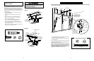
Alternate Wall Mount
Sensor
with wire
Indicator Light
Indicator Light
Inside
Garage
Wall
Alternate Floor Mount
Mounting Bracket
with Slot
Attach with
concrete anchors
(not provided)
Mounting Bracket
with Square Holes
"C" Wrap
Sensor with wire
Garage
Floor
13
Hardware Shown Actual Size
Figure 1
Figure 4
Figure 5
Figure 3
Figure 2