


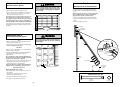


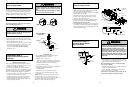


To reduce the risk of electric shock, your garage door
opener has a grounding type plug with a third grounding
pin. This plug will only fit into a grounding type outlet.
If the plug doesn't fit into the outlet you have, contact a
qualified electrician to install the proper outlet.
•If permanent wiring is required by your local code,
refer to the following procedure:
Right
Wrong
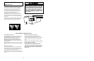
Ground Tab
Green
Ground Screw
Ground Wire
BlackWire
Permanent Wiring
Connection
White Wire
Black
Wire
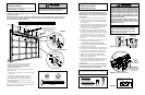
Installation Step 8
Electrical Requirements
To make a permanent connection through the 7/8" diam.
hole in the top of the opener (according to local code):
• Remove the opener cover screws and set the cover aside.
• Remove the attached 3-prong cord.
• Connect the black (line) wire to the screw on the brass
terminal; the white (neutral) wire to the screw on the
silver terminal; and the ground wire to the green
ground screw. The opener must be grounded.
• Reinstall the cover.
18
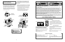
To prevent electrocution or fire, installation and wiring
must be in compliance with local electrical and building
codes.
Do NOT use an extension cord, 2-wire adapter, or change
the plug in any way to make it fit your outlet.
To avoid installation difficulties,
do not run the opener until Step 9 below.
To prevent electrocution, remove power from the
garage door opener and from the circuit you plan to
use for the permanent connection.
WARNING
CAUTION
WARNING
WARNING
CAUTION
WARNING
Installation Step 9
Complete Safety Reversing Sensor
Installation
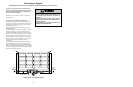
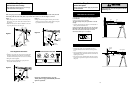
Installation Step 10
Install the Lights and Lens
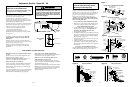
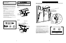
Installation Step 11
Attach the Manual Release
Rope and Handle
Do not use the red handle to pull the door open or
closed. The rope knot could become untied and you
could fall. Use the manual release only to disengage the
trolley and, if possible, only when the door is closed.
Garage doors are heavy. If the door is open when the
handle is pulled, the door could close inadvertently if it is
not properly balanced. Serious injury may result to
persons under the door. Make sure the doorway is clear
of persons and obstructions before pulling handle when
door is open.
• Thread one end of the rope through the hole in the top
of the red handle so “NOTICE” reads right side up as
shown. Secure with an overhand knot.
The knot should be at least 1" from the end of the
rope to prevent slipping.
• Thread the other end of the rope through the hole in the
release arm of the outer trolley.
• Adjust rope length so the handle is 6 feet above the
floor. Secure with an overhand knot .
If it is necessary to cut the rope, heat seal the cut end
with a match or lighter to prevent unraveling.
Trolley
NOTICE
Overhand
Knot
Manual
Release Handle
Rope
Overhand
Knot
Trolley
Release Arm
19
WARNING
CAUTION
WARNING
• Install a 100 watt maximum light bulb in each socket.
The lights will turn ON and remain lit for
approximately 4-1/2 minutes when power is connected.
Then the lights will turn OFF.
• Insert bottom lens tabs into slots on chassis and tilt
towards chassis to engage top tabs, then drop down
gently into place. (See illustration.)
• To remove, lift lens up and gently tilt slightly outward
and down, then pull out to clear bulbs. Use care to
avoid snapping off bottom lens tabs.
• If the bulbs burn out prematurely, replace with standard
neck Garage Door Opener bulbs. (Fluorescent bulbs are
not recommended because of possible interference with
receiver/transmitter signals.)
100 Watt Max.
Light Bulb
Bottom Lens Tab
Top Lens Tab
Top Lens Slot
Bottom Lens Slot
Light Socket
Insert Bottom Lens Tabs First
Chassis
Lens
CONTROL
CENTER
CONTROL
CENTER
Aligning the Safety Sensors
• Plug in the opener. Green indicator lights in both the
sending and receiving eyes will glow steadily if wiring
connections and alignment are correct.
The sending eye indicator light will glow regardless of
alignment or obstruction. If the indicator light is off, dim,
or flickering in the receiving eye (and the invisible light
beam path is not obstructed), alignment is required.
• Loosen the sending eye wing nut and re-adjust, aiming
directly at the receiving eye. Lock in place.
• Loosen the receiving eye wing nut and adjust sensor
vertically and/or horizontally until it receives the
sender’s beam. When the green indicator light glows
steadily, tighten the wing nut.
Trouble Shooting
1. If the sending eye indicator light does not glow
steadily after installation, check for:
• Electric power to the opener.
• A short in the white or white/black wires. These can
occur under staples or at screw terminal connections.
• Incorrect wiring between sensors and opener.
• An open wire (wire break).
2. If the sending eye indicator light glows steadily but the
receiving eye indicator light doesn't:
• Check alignment.
• Check for an open wire to the receiving eye.
3. If the receiving eye indicator light is dim, realign
either sensor.
NOTE: When the invisible beam path is obstructed or
misaligned while the door is closing, the door will
reverse. If the door is already open, it will not close. The
opener lights will flash 10 times. (If bulbs are not
installed, 10 clicks are audible.) See page 12.