


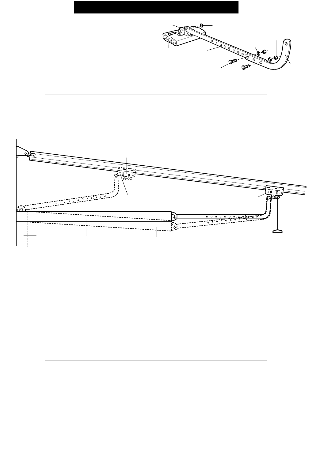
Door Arm
Fully Open
Trolley
Closed
Door
Open Door
Door with
Backward Slant
Door Arm
Connector Hole
Door Arm
Connector Hole
Fully Closed
Trolley
Door Arm
Nuts
5/16"-18
Lock
Washers
5/16"
Ring
Fastener
Straight
Arm
Screws
5/16"-18x7/8
Door
Bracket
Clevis Pin
5/16"x1-1/4"
Curved
Door Arm
14
Figure 6
1/4-20 x 1-1/2"
Hex Bolt
"C" Wrap
Sensor
with Wire
Wing
Nut
Indicator
Light
1/4-20 x 1-1/2"
Hex Bolt
Wing Nut
Hardware Shown Actual Size
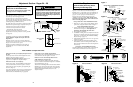
Installation Step 4 (Continued)
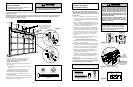
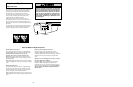
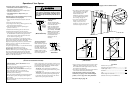
Install the Safety Reversing Sensor
Invisible Light Beam
Protection Area
Sensor
Sensor
Bell Wire
Foam
Packaging
Carton
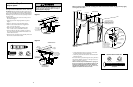
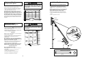
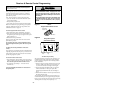
2. Run wires along channels
to power unit and pull taut.
1. Run wires from sensors to end of rail
at the door header. Cross & twist here to
help contain wires in channels on top of rail.
3. Thread wires through tabs
on top of Drive Shaft Cover.
4. With screwdriver blade,
tuck wires snugly into channels.
Header
Bracket
Header
Wall
Sensor
Wire
Twist
Wires
Sensor
Wire
Rail
Channel
Figure 7
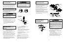
7. Center each sensor unit in a “C”- wrap with lenses
pointing toward each other across the door (see
Figure 6).
8. Secure sensors with the hardware shown. Finger
tighten the wing nut on the receiving eye to allow for
final adjustment. Securely tighten the sending eye
wing nut.
Recommended Wire Routing
1. Using insulated staples, run the wires from both
sensors to the rail at the door header (see Figure 7).
2. Cross and twist the two wires where they meet the rail
(see inset A). Run the wires inside the channels at the
top of the rail, along each side, to the power unit and
pull taut (see inset B). Do not use the lower (trolley)
channels.
NOTE: If your access door is near the garage door,
you may choose to install the door control at this
time and run the door control wire along the rail
with the sensor wires. Use one rail channel for the
wall control wire and the other channel for both
sensor wires. If you choose this option, follow
instructions 1-3 on page 17 now.
3. Thread the wires through the tabs on top of the drive
shaft cover.
4. With your screwdriver tip, tuck the wires snugly into
the rail channels. You will complete the wiring in
Installation Step 7.
A
B
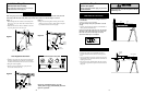
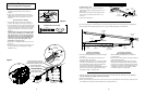
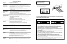
All ONE-PIECE Doors
Assemble the Door Arm:
• Fasten the straight and curved door arm sections
together to the longest possible length (with a 2 or 3
hole overlap).
• With the door closed, connect the straight door arm
section to the door bracket with the 5/16"x1-1/4"
clevis pin.
• Secure with a ring fastener.
On one-piece doors, before connecting the door arm to the trolley the travel limits must be adjusted. Limit adjustment
screws are located on the right side panel as shown on page 24. Follow adjustment procedures below.
Adjustment Procedures for One-Piece Doors
Open Door Adjustment:
Decrease UP Travel Limit
• Turn the UP limit adjustment screw counter-clockwise
5 1/2 turns.
• Press the Door Control push bar. The trolley will
travel to the fully open position.
• Manually raise the door to the open position (parallel
to the floor), and lift the door arm to the trolley. The
arm should touch the trolley just in back of the door
arm connector hole. Refer to the fully open
trolley/door arm positions in the illustration. If the arm
does not extend far enough, adjust the limit further.
One full turn equals 2" of trolley travel.
Closed Door Adjustment:
Decrease DOWN Travel Limit
• Turn the DOWN limit adjustment screw clockwise
5 complete turns.
• Press the Door Control push bar. The trolley will travel
to the fully closed position.
• Manually close the door and lift the door arm to the
trolley. The arm should touch the trolley just ahead of
the door arm connector hole. Refer to the fully closed
trolley/door arm positions in the illustration. If the arm
is behind the connector hole, adjust the limit further.
One full turn equals 2" of trolley travel.
Connect the Door Arm to the Trolley:
• Close the door and join the curved arm to the connector hole in the trolley with the remaining clevis pin. It may be
necessary to lift the door slightly to make the connection.
• Secure with a ring fastener.
• Run the opener through a complete travel cycle. If the door has a slight "backward" slant in full open position as shown
in the illustration, decrease the UP limit until the door is parallel to the floor.
23