


31
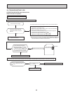
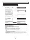
OPERATING PROCEDURE
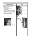
PHOTOS
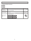
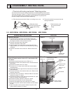
1. Removing the panel
(1) Press and unlock the knobs on both sides of the front
panel and lift the front panel until it is level, and then pull
the hinges forward to remove the front panel.
(2) Remove the screw caps of the panel.
Remove the screws of the panel.
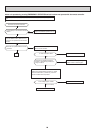
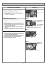
(3) Hold the lower part of both ends on the panel and pull it
slightly toward you, and then remove the panel by pushing
it upward.
(4) Remove the screw of the corner box. Remove the corner
box.
2. Removing the electrical box, the electronic control P.C.
board, the power monitor receiver P.C. board and the SW
P.C. board
(1) Remove the panel and corner box. (Refer to 1.)
(2) Remove the screw of the electrical cover. Remove the elec-
trical cover.
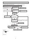
(3) Remove the screw of the V.A. clamp.
(4) Remove the V.A. clamp, then remove the indoor/outdoor
connecting wire.
(5) Disconnect TAB of the ground wire connected to the indoor
heat exchanger.
(6) Remove the screw of the electrical side cover. Remove the
electrical side cover.
(7) Disconnect all the connectors, TAB and TAB4 on the indoor
electronic control P.C. board.
(8) Remove the screw on lower side of the electrical box. (See
photo 3) Remove the electrical box.
(9) Remove the indoor electronic control P.C. board.
(
10
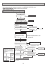
) Remove the SW holder from the electrical box.
(
11
) Open the SW holder and pull out the SW P.C. board.
(
12
) Remove the power monitor receiver holder from the electri-
cal box.
(
13
) Open the power monitor receiver holder and pull out the
power monitor receiver P.C. board.
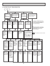
DISASSEMBLY INSTRUCTIONS
10
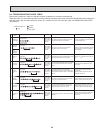
(1) Slide the sleeve and check if there is a locking lever or not.
(2) The terminal with this connector has the
locking mechanism.
Slide the sleeve.
Pull the terminal while
pushing the locking
lever.
Hold the sleeve, and
pull out the terminal
slowly.
The terminal which has the locking mechanism can be detached as shown below.
There are two types ( Refer to (1) and (2)) of the terminal with locking mechanism.
The terminal without locking mechanism can be detached by pulling it out.
Check the shape of the terminal before detaching.
<"Terminal with locking mechanism" Detaching points>
Connector
Sleeve
Locking lever
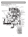
10-1. MSZ-D30NA MSZ-D36NA MSY-D30NA MSY-D36NA
Photo 1
Photo 2
Front panel
Screw of
electrical side
cover
Screws
Power monitor
receiver holder
Screw of the
corner box
SW holder
Ground wire to indoor
heat exchanger
Screw of elec-
trical cover
Screw of V.A.
clamp
Water cut