


8
Chateau™ Decorative Gas Appliance
20009543
Always check for gas leaks with a mild
soap and water solution applied with a
brush no larger than 1” (25mm). Never ap-
ply soap and water solution with a spray
bottle. Do not use an open flame for leak
testing.
The fireplace valve must not be subjected
to any test pressures exceeding 1/2 psi.
Isolate or disconnect this or any other gas
appliance control from the gas line when
pressure testing.
The gas control is equipped with a captured screw type
pressure test point, therefore it is not necessary to pro-
vide a 1/8” test point up stream of the control.
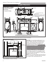
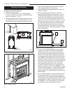
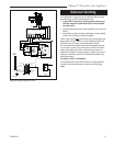
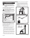
When using copper, use only approved fittings.
Always
provide a union when using black iron pipe so the gas
line can be easily disconnected for burner servicing. A
union may not be behind a wall. (Fig. 8) See the gas
specifications for pressure details and ratings.
The fireplace, when installed, must be elec-
trically connected and grounded in accord-
ance with local codes or, in the absence
of local codes, with the current CSA C22.1
Canadian Electrical Code or the national
electrical code ANSI/NFPA No. 70 in the
USA.
It is strongly suggested that the wiring of
the Electrical Junction Box be carried out
by a licensed electrician. The box should
be near the valve box assembly to plug the
cord into.
Ensure the power to the supply line has
been disconnected before commencing
this procedure.
Electrical Junction Box (E Units Only)
Do not wire the remote ON/OFF wall switch
for this gas appliance into a 120V power
supply.
The unit is equipped with an ON/OFF rocker switch at
the valve box assembly. If a wall switch is desired, fol-
low these instructions.
1. The valve box is equipped with two knockouts at
the top right and left corners. The right knockout is
designed to run the wall switch wires to the valve.
Use Romex connectors when running wires through
the valve box where the knockouts are located.
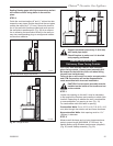
2. Attach the wire to the ON/OFF switch and install the
switch into the receptacle box.
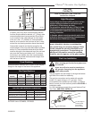
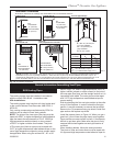
3. Connect the other end of the wire to the gas control
valve. (Fig. 9)
Remote ON/OFF Switch
H
I
L
O
O
N
O
F
F
E
A
P
I
L
O
T
THTP
TP
TH
Fig. 9 Remote switch wiring diagram for R models.
Remote ON/OFF
Switch
Gas Control Valve
FP1366
This appliance may be fitted with a Honeywell ignition
module. The unit is shipped from the manufacturer with
an ON/OFF switch. The ON/OFF switch is located in
the valve box assembly. If desired a wall switch may be
used.
Installation of the remote ON/OFF switch on electronic
ignition units:
1. The valve box is equipped with two knockouts at the
top right and left corners. The right knockout is de-
signed to run the wall switch wires to the valve. The
left knockout is designed for wiring the electronic
unit (E model) to 120v with proper grounding. Use
Romex connectors when running wires through the
valve box where the knockouts are located.
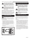
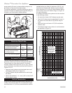
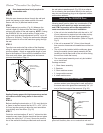
2. Attach the wire to the ON/OFF switch and install the
switch into the receptacle box. (Fig. 10)
3. Connect the White wire from the wall switch to the
Black wire from the transformer, using an approved
wire nut or terminal. Connect the Black wire from the
wall switch to the Black wire running from the #6 po-
sition of the ignition module, also using an approved
wire nut or terminal.
Electronic Gas Control Valve