


15
Chateau™ Decorative Gas Appliance
20009543
Sealing firestop gaps with high temperature sealant
will restrict cold air being drawn in around fire-
place.
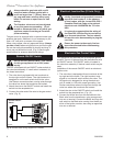
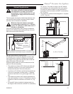
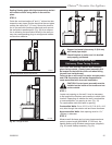
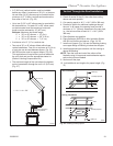
STEP 8
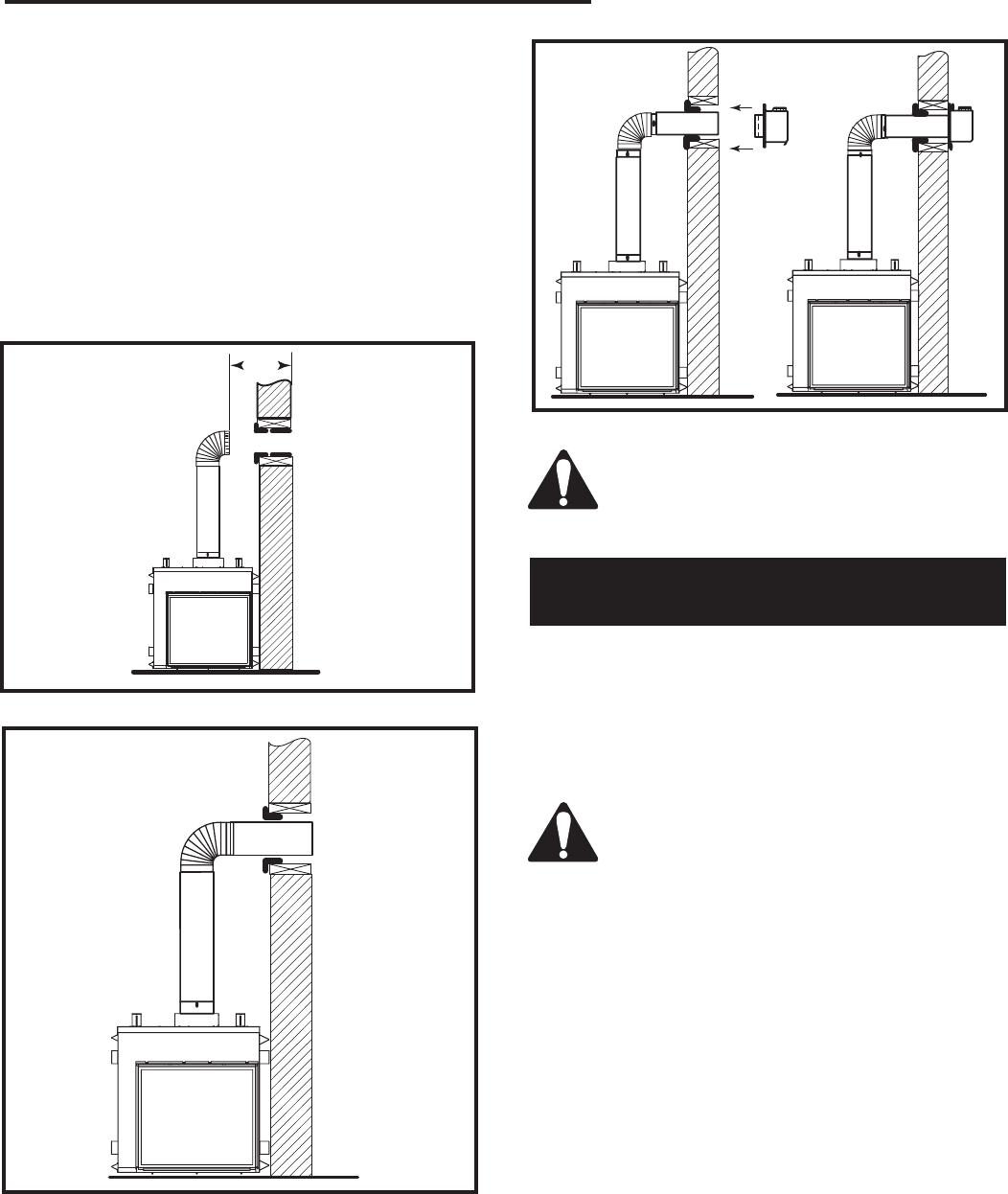
Guide the vent terminations 8” and 11” collars into their
respective vent pipes. Double check that the vent pipes
overlap the collars by 2” (51 mm). Secure the termina-
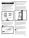
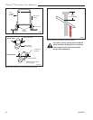
tion to the wall with screws provided and caulk around
the wall plate to weatherproof. (Fig. 24) As an alterna-
tive to screwing the termination directly to the wall you
may also use expanding plugs or an approved exterior
construction adhesive.
FP1458
Fig. 23 Through the wall.
FP1457
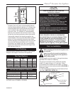
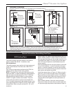
Fig. 22 Horizontal length requirement.
X
FP1460
Fig. 24 Secure termination to wall.
Support horizontal pipes every 3’ (914 mm)
with metal pipe straps.
Check fireplace to make sure it is levelled
and properly positioned.
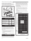
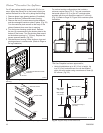
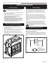
Sidewall Installation with
Stationary Glass Facing Outside
CAUTION: Unit must be installed with stationary
glass facing outside. (Control panel assembly will
be located on the left side of the unit when facing
the unit form inside house.)
Failure to do so will result in a major reconstruction
and CFM Corporation will not be responsible for
costs associated with incorrect installation.
CAUTION: Control panel assembly must be
installed on the inside of the house and not
on the outside.
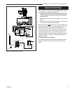
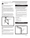
STEP 1
Locate vent opening on the wall. It may be necessary
to first position the fireplace and measure to obtain hole
location. Depending on whether the wall is combustible
or noncombustible, cut opening to size. (Fig. 19)
For combustible walls first frame in opening.
Combustible Walls: Cut a 16
¹⁄₄”H x 16¹⁄₄” W (413 x 413
mm) hole through the exterior wall and frame as shown.
Noncombustible Walls: Hole opening must be 11
¹⁄₄”
(286mm) in diameter.
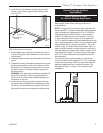
STEP 2
Measure wall thickness and cut zero clearance sleeve
parts to proper length (MAXIMUM 12”/305 mm). As-
semble sleeve using #8 sheet metal screws (supplied).
(Fig. 20) Install firestop assembly. (Fig. 30)