


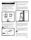

17
Chateau™ Decorative Gas Appliance
20009543
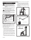
Vertical Through-the-Roof
Applications
Use of Restrictor Plate
for Vertical Venting Application
The primary purpose for the vent restrictor is to regain
flame height under certain venting conditions as
outlined below.
NOTE: The joints of the inner pipe (flue pipe) must be
taped with 550°F or higher temperature metal adhesive
tape that meets the requirements of F.A.R. 25.853(a).
High temperature sealant milpack or stove cement
of 550°F or higher could be used instead. The joints
of The outer pipe (fresh air pipe) must be taped with
315°F or higher temperature metal adhesive tape or the
use of high temperature milpack or stove cement would
be applicable. When using the unitized 30°, 45° or 90°
elbows, apply 1/4” bead of high temperature, 550°F or
higher, sealant (milpack or stove cement) to the joint of
the inner pipe (flue pipe) and the straight section as it is
impossible to be taped. The outer pipe must be taped
with 315°F high temperature metal adhesive tape for
proper sealing.
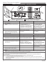
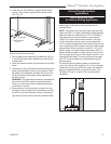
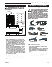
For vertically venting either propane or natural gas
units, with vertical vent heights of 12’ (3.7m) or greater,
(measured from the top of the flue collar) the restrictor
plate as supplied with this unit should be used. (Fig.
28) Refer to Page 21, Figure 37 for restrictor plate
installation.
X
FP1461
Fig. 28 Restrictor plate use in straight up installation.
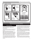
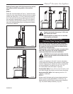
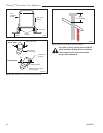
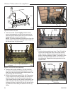
2. Install the two (2) brackets, using the sheet metal
screws, at the bottom right and left corners of the
unit. (Fig. 27)
FP1481
install brackets
4/04
Bracket
Sheet Metal
Screws
FP1481
Fig. 27 Use sheet metal screws to attach brackets to existing
holes under glass frame assembly.
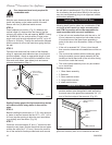
3. Set the glass frame assembly provided with your kit
in front of the glass frame assembly on the unit (the
outside side).
4. Have the machine screws provided with the kit within
reach.
5. Unfasten the two (2) machine screws that secure the
glass frame assembly to the unit and discard. Slide
the glass frame assembly provided with the kit over
the surround around the glass frame assembly on
the side and top.
WARNING: The glass frame assembly provided with
the unit must be left in place for proper operation.
Failure to do so could cause property damage and
malfunction of the unit.
6. Fasten the two (2) long machine screws at the top
through the two (2) glass frame assemblies and fas-
ten the two (2) short machine screws at the bottom
right and left corner into the bracket installed earlier.