


16
Chateau™ Decorative Gas Appliance
20009543
FP1461
thru wall trim
3/17/04 djt
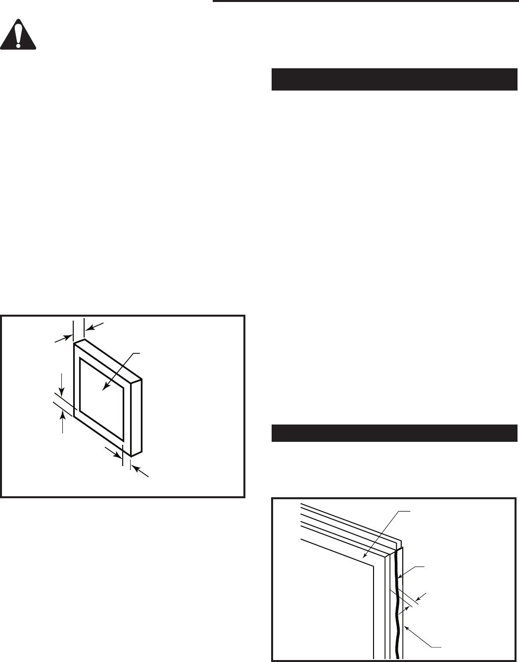
2”
(51mm)
1”
(25mm)
Min.
1” (25mm) Min.
16¹⁄₄” x 16¹⁄₄”
(413 x 413mm)
Opening
FP1461
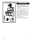
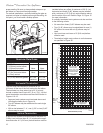
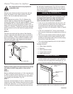
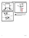
Fig. 25 A 2” (51mm) thick trim is required around opening.
Zero clearance sleeve is only required for
combustible walls.
STEP 3
Slide the zero clearance sleeve through the wall and
install the firestop on the inside surface of the wall.
Secure with four (4) #8 sheet metal screws.
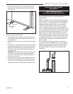
STEP 4
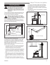
Place fireplace into position. (Fig. 21) Measure the
vertical height (X) required from the base of the flue
collars to the center of the wall opening. NOTE: If using
the SK8DVSK Kit, the vertical section of pipe is tele-
scopic and could provide adjustment from 24” up to 40”
(610mm to 1016mm). Through the wall section shipped
with the starter kit will not be used when going through
the wall.
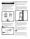
STEP 5
Tape the inner and outer flue collars of the fireplace
using UL approved metal adhesive tape to ensure the
joints are sealed. Attach an appropriate length of vent
pipe to the fireplace. Follow with the installation of the
inner and outer elbow, tape elbow joints and secure
joints as described on Page 11.
Sealing firestop gaps with high temperature sealant
will restrict cold air being drawn in around fire-
place.
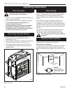
STEP 6
Before installing the termination, a 2” (51 mm) thick trim
or frame is required around the the 16¹⁄₄” x 16¹⁄₄” (413 x
413 mm) square opening to allow the vent termination
to go directly onto the elbow. (Fig. 25)
STEP 7
Guide the vent terminations 8” and 11” collars into their
respective vent pipes. Double check that the vent pipes
overlap the collars by 2” (51 mm). Secure the termina-
tion to the wall with screws provided and caulk around
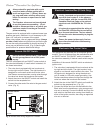
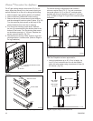
Installing the 38S2VDK Door
When installing the DVT38S2 on an outside wall, the
following steps must be taken into consideration. Fail-
ure to do so will result in a major reconstruction
and CFM Corporation will not be responsible for
costs associated with incorrect installation.
• If the unit is to be installed flush with the wall, a 1/4”
(6 mm) clearance is required on both sides and top
of surround around the glass frame assembly in
order for the door to be accessible. (Refer to Page 4,
Fig. 2)
• If the unit is recessed 3/4” (19 mm) from the wall,
then no extra clearances are needed around the sur-
round.
• The unit must be installed with the stationary glass
facing the outside (control panel assembly will be
located on the left hand side of the unit when facing
the unit from inside the house).
• The control panel assembly must only be installed
on an inside wall.
Package contents:
• 1, Glass frame assembly
• 2, Brackets
• 2, Short machine screws
• 2, Long machine screws
• 4, sheet metal screws
Installation Procedure
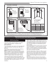
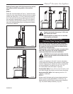
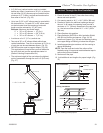
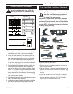
1. If the unit is installed flush with the wall, a high tem-
perature sealant must be applied to seal around the
surround around the glass frame assembly 3/4” (19
mm) of the front edge of the surround. (Fig. 26)
the wall plate to weatherproof. (Fig. 25) As an alterna
-
tive to screwing the termination directly to the wall you
may also use expanding plugs or an approved exterior
construction adhesive.
• • • • • • • • • • • •
• •• •••••• • •••• • •• • ••••••••••••••••••••
• •• • • • • •
3/4"
(19mm)
Glass Frame As-
sembly
High Temperature
Sealant
Surround
FP1480
Fig. 26 Apply high temperature sealant on surround around
glass frame assembly when unit is installed flush with wall.