


23
Chateau™ Decorative Gas Appliance
20009543
Ceramic Refractory Installation
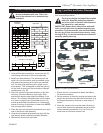
The ceramic refractories are fragile and
should be handled with care. Due to the
size of the refractories, an assistant may
be helpful.
1. Using a Robertson screwdriver, remove the two (2)
nuts holding each fettle to the burner assembly.
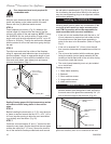
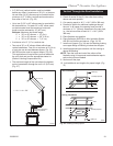
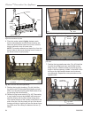
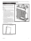
2. Identify the side refractory. The refractory with the
small cut out at the bottom must be installed on the
side where the plumbing for the pilot and manifold
are. The other side refractory has a larger cut out
at the bottom. This is designed to allow the opening
for the fresh air coming to the combustion chamber
unobstructed. (Fig. 40)
3. Start with either the right side refractory or left side
refractory. Hold the refractory at an angle. Slide
and seat the bottom edge toward the bottom of the
firebox. Tilt it carefully toward the side until the piece
is in place. Using the two (2) brackets and four (4)
screws provided with the refractory kit, fasten each
bracket to the top of the firebox on each side. NOTE:
Use existing holes in firebox.
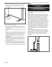
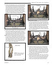
4. Place the right and left hearth refractories at on each
side of the burner tube assembly.
5. Install the end hearth refractories and align with the
right and left hearth refractories already installed.
6. Reinstall the burner tube and fettle.
FP1580
DVT38s2
refractory
6/05
Refractory,
Left Side
Refractory,
Right Side
FP1580
Fig. 40 Ceramic refractory panels.
Refractory, Left Hearth
Refractory, Right Hearth
Refractory, End
Hearth
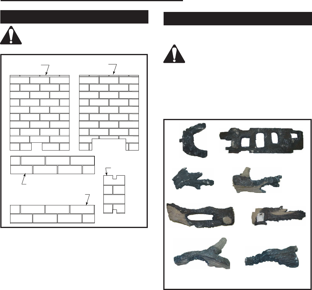
Log, Lava Rock and Ember Placement
Unpack the logs from packaging and remove each log
from its wrapping material.
The logs are fragile and should be handled
with care. Keep the packaging materials
out of the reach of children and dispose of
the material in a safe manner.
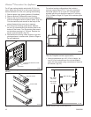
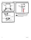
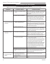
IMPORTANT: Review these instructions and famil-
iarize yourself with each log before beginning log
placement. Find the notches, pins and indentations
on each log. Follow the instructions closely, using
the Log ID (Fig. 41) and the illustrations to assist in
correctly placing each log.
Log Pilot Plumbing
Log Overlay
Log Grate/Burner
Tube (2)
Log Left Grate (2)
Log Middle
Log Right Grate
Log Front Right (2)
Log Front Upper
Right (2)
LG421
Fig. 41 DVT38S2 log identification.
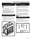
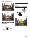
1. Ensure the four (4) screws that attach the fettle to
the burner are secure.
2. Set the andirons in place by hooking the tabs on the
back of the andirons over the webs of the fettle. (Fig.
42) Repeat process for andirons on both sides of
burner.
3. Place the volcanic rock over the lower refractory in
front of each burner tube assembly and around the
burner assembly as desired. (Fig. 43) Do not ob-
struct fresh air inlet with volcanic rock.