


34
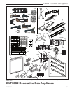
Chateau™ Decorative Gas Appliance
20009543
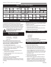
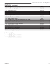
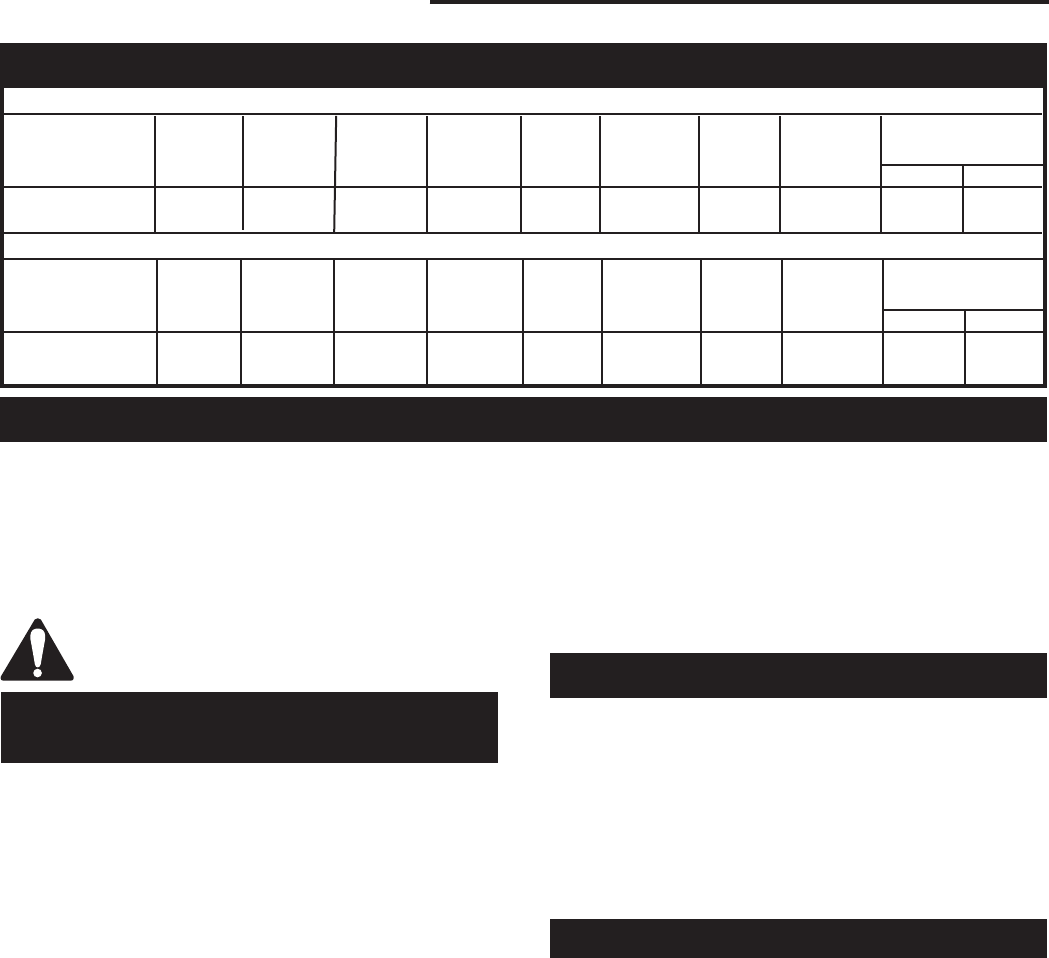
Conversion to Natural Gas
Kit # Burner
20009164 Burner Housing/ Burner Burner Input (BTU/hr)
Model Housing Part # Pilot* Part # Tube Part # Tube Part # Min. Max.
DVT38S2RP/EP #38 20009310 #38 20009310 #45 20010169 #45 20010169 45,000 56,000
(.1015”) (.1015”) (.082”) (.082”)
Table 1 Injector Orifice Size Matrix
Conversion to LP
Kit # Burner
20009162 Burner Housing/ Burner Burner Input (BTU/hr)
Model Housing Part # Pilot* Part # Tube Part # Tube Part # Min. Max.
DVT38S2RN/EN #55 30000333 #54 20000130 #57 20004587 #57 20004587 38,000 56,000
(.052”) (.055”) (.043”) (.043”)
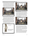
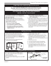
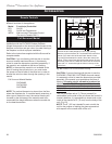
Maintenance
Burner and Burner Compartment
It is important to keep the burner and the burner
compartment clean. At least once per year the logs and
lava rock/ember material should be removed and the
burner compartment vacuumed and wiped out. Remove
and refit the logs as per the instructions in this manual.
Always handle the logs with care as they
are fragile and may also be hot if the
fireplace has been in use.
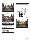
Cleaning the Standing
Pilot Control System
The burner and control system consist of:
• burner tube • gas orifice
• pilot assembly • thermopile
• gas valve
Most of these components may require only an
occasional checkup and cleaning and some may
require adjustment. If repair is necessary, it should
be performed by a qualified technician.
1. Turn off pilot light at gas valve.
2. Allow fireplace to cool if it has been operating.
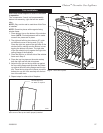
3. Remove window frame assembly. (Refer to Window
Frame Assembly Removal section.)
4. Remove logs.
5. Vacuum burner compartment especially around
orifice primary air openings.
6. Visually inspect pilot. Brush or blow away any dust
or lint accumulation.
7. Reinstall logs.
8. Ignite pilot - Refer to Lighting Instructions.
9. Reinstall window frame assembly.
To obtain proper operation, it is imperative that the pilot
and burner’s flame characteristics are steady, not lifting
or floating.
Typically, the top 3/8” to 1/2” of the thermopile/sensing
electrode should be engulfed in the pilot flame. (Refer
to Page 26, Figure 54)
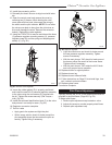
To adjust pilot burner: (by qualified service technician)
1. Remove pilot adjustment cap
2. Adjust pilot screw to provide properly sized flame.
3. Replace pilot adjustment cap.
Cleaning Electronic Ignition System
The Electronic Ignition burner/control system consists
of:
• main burner
• gas orifice
• pilot burner
• 24VAC valve with transformer
Taking care of the Electronic Ignition units is identical to
taking care of the Standing Pilot models.
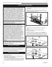
Battery Replacement for Ignitor Module
1. Open control panel box door.
2. Remove the extension knob(s).
3. Remove the valve cover by removing the two (2)
screws securing the valve cover plate to the box.
While holding the valve cover plate with one hand,
disconnect the wiring to the switch and the pilot
indicator. NOTE: Do not allow the valve cover plate
to hang from the pilot indicator wires as this could
damage the wires.
4. Replace the battery (AA) in the ignitor module lo
-
cated at the top left corner.
5. Replace wires, valve cover, extension knob(s) in
reverse order. NOTE: The pilot indicator body is
labelled +/-, make sure the positive wire on the pilot
indicator goes to ground and the negative goes to
the plug between the valve and the thermocouple.