


12
Vermont Castings Madison
30001453
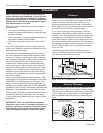
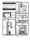
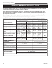
Madison 1655 Series Clearance Chart
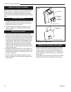
Use the chart below together with the diagrams on the next page to determine the minimum clearance required for
your particular installation. In any case, it is always advisable to locate the stove as far away from walls as possible
in order to take full advantage of the radiant properties of cast iron.
Stove clearances are measured between the cast iron Top Plate of the stove and the combustible surface. Note
that the cast iron back on the Madison protrudes 5” (127mm) out from the stovetop, and will therefore be closer to
the wall than the top of the stove.
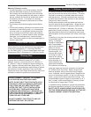
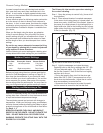
Chimney Connector clearances are measured between the connector surface and the combustible surface. For
Douible-wall Chimney Connector, use the manufacturer’s listed clearance specification.
Use NFPA 211 default clearance or manufacturer’s installation specifications for those configurations not tested.
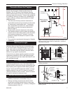
UNPROTECTED SURFACES PROTECTED SURFACES
Side Rear Corner Side Rear Corner
Top exit, no heat shields
Top exit, heat shields on stove,
no shields on single wall con-
nector
Top exit, heat shield on stove,
heat shield on single wall con-
nector
Top exit, heat shield on stove,
double wall chimney connector
Rear exit, no heat shields
Rear exit, heat shields
STOVE CLEARANCE
Without Connector Heat
Shields
With Connector Heat Shields
CHIMNEY CONNECTOR
CLEARANCE
* A distance of 48” must be maintained between the stove and moveable combustible items such as drying
clothes, furniture, firewood, etc.
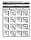
Corner In-
stallation
Parallel Installation
Corner In-
stallation
Parallel Installation
UNPROTECTED SURFACE / Vertical PROTECTED SURFACE / Vertical
FRONT CLEARANCE
TO COMBUSTIBLES*
ALL INSTALLATIONS
48” (1220mm)
UNPROTECTED SURFACE / Horizontal PROTECTED SURFACE / Horizontal
Single-wall Connector
A 21”
(533 mm)
B 24”
(610 mm)
C 21”
(533 mm)
M 21”
(533 mm)
N 22”
(559 mm)
O 18”
(457 mm)
D 12”
(305 mm)
E 14”
(356 mm)
F 10”
(250 mm)
19” (483mm)
13” (330mm)
23” (584mm) 23” (584mm)
G 21”
(533 mm)
H 24”
(610 mm)
I 21”
(533 mm)
J 12”
(305 mm)
K 14”
(356 mm)
L 10”
(250 mm)
P 12”
(305 mm)
R 8”
(203 mm)
Q 14”
(356 mm)
T 12”
(305 mm)
S 16”
(406 mm)
W 11”
(279 mm)
U 18”
(457 mm)
N/A
N/A
X 8”
(203 mm)
V 12”
(305 mm)
Z 20”
(508 mm)
Y 18”
(457 mm)
BB 15”
(381 mm)
AA 12”
(305 mm)
N/A
N/A
DD 18”
(457 mm)
CC 16”
(406 mm)
FF 12”
(305 mm)
EE 12”
(305 mm)