


10
Vermont Castings Madison
30001453
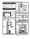
Wall Shields
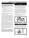
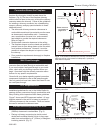
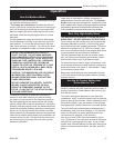
Wall shields should be constructed of 24 gauge or
heavier sheet metal, or another noncombustible mate-
rial such as 1/2” (13mm) insulation board (Fig. 14) or
common brick “laid on flat,” with the 3¹⁄₂" (89mm) side
down.
Shields must be spaced out from the combustible sur-
face 1" (25mm) on noncombustible spacers. The spac-
ers should not be directly behind the stove or chimney
connector.
Air must be able to flow between the wall and the
shield. At least 50% of the bottom 1" (25mm) of the
shield should be open and the shield must be open at
the top.
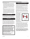
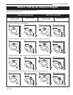
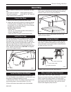
The following examples of wall shield construction illus-
trate common designs used to safely achieve reduced
clearances to combustible wall materials.
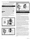
Parallel installation, vertical chimney connector,
two wall shields. Fig. 15: Reduced clearances for
both rear and side walls. Wall shields may meet at
corner if desired. Shielding for connector is centered
behind connector.
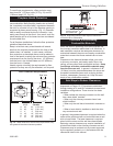
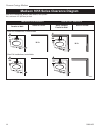
Parallel installation with rear wall pass-through, two
wall shields. Fig. 16: Reduced clearances for both
rear and side walls. Wall shields may meet at corner if
desired. Shielding for connector is centered behind con
-
nector. Wall pass-through must comply with codes.
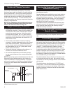
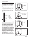
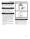
Corner installation, vertical chimney connector, two
wall shields. Fig. 17: Reduced side clearances. Wall
shields MUST meet at corner.
Parallel installation with rear exit, rear wall pass-
through, rear wall shield. Fig. 18: Reduced clear-
ances for rear wall. Shielding for connector is centered
behind connector. Wall pass-through must comply with
codes.
Fig. 15 Parallel installation, vertical chimney connector, two
wall shields.
C
C
C
B
A
B
ST550
Madison
wall shield
11/00
A
C
ST550
A = 48” (1219 mm)
B = Max. - C
C = 1” (25 mm)
Fig. 16 Parallel installation with rear wall pass-through, two
wall shields.
A
B
C
B
A
C
ST551
Madison
Wall shield
BB
11/00
ST551
A = 48” (1219 mm)
B = 48” (1219 mm)
C = 1” (25 mm)
Fig. 17 Corner installation, vertical chimney connector, two
wall shields.
B
B
C
C
A
A
ST552
Madison
Wall shield
cc
11/00
C
C
ST552
A = 48” (1219 mm)
B = Max. - C
C = 1” (25 mm)
C
A
B
ST564Madison
wall shield
11/00
A = 48” (1219 mm)
B = 48” (1219 mm)
C = 1” (25 mm)
ST564
Fig. 18 Parallel installation, rear wall pass through, rear wall
shield.
ST248a
wall shield construction
12/14/99 djt
Fig. 14 Approved Wall shield construction
Air flow
Wall shield
Air flow
Stud wall
framing
Noncombustible
spacers and
fasteners
Drywall
Metal Spacer
Shield
ST248a