51
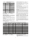
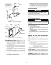
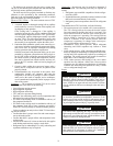
The bulb must be secured to the pipe using a copper strap.
The use of heat transfer paste between the bulb and the pipe
will also help ensure optimum performance.
The bulb must also be properly insulated to eliminate any
influence on valve operation by the surrounding conditions.
Cork tape is the recommended insulation as it can be molded
tight to the bulb to prevent air infiltration.
Causes of TXV Failure
— The most common causes of TXV
failure are:
1. A cracked, broken, or damaged sensing bulb or capillary
can be caused by excessive vibration of the capillary dur-
ing shipping or unit operation.
If the sensing bulb is damaged or if the capillary is
cracked or broken, the valve will be considered failed and
must be replaced. Replacement of the TXV “power head”
or sensing bulb, capillary, diaphragm assembly is possible
on some TXVs. The power head assembly screws onto
most valves, but not all are intended to be replaceable. If
the assembly is not replaceable, replace the entire valve.
2. Particulate debris within the system can be caused by sev-
eral sources including contaminated components, tubing,
and service tools, or improper techniques used during
brazing operations and component replacement.
Problems associated with particulate debris can be com-
pounded by refrigerant systems that use POE (polyol es-
ter oil). POE oil has solvent-like properties that will clean
the interior surfaces of tubing and components. Particu-
lates can be released from interior surfaces and may mi-
grate to the TXV strainer, which can lead to plugging of
the strainer.
3. Corrosive debris within the system may happen after a
failure, such as a compressor burn out, if system was not
properly cleaned.
4. Noncondensables may be present in the system. Non-
condensables includes any substance other than the
refrigerant or oil such as air, nitrogen, or water. Contami-
nation can be the result of improper service techniques,
use of contaminated components, and/or improper evacu-
ation of the system.
Symptoms
— The symptoms of a failed TXV can be varied
and will include one or more of the following:
• Low refrigerant suction pressure
• High refrigerant superheat
• High refrigerant subcooling
• TXV and/or low pressure tubing frosting
• Equalizer line condensing and at a lower temperature than
the suction line or the equalizer line frosting
• FP1 faults in the heating mode in combination with any of
the symptoms listed above
• FP2 faults in the cooling mode in combination with any of
the symptoms listed above. Some symptoms can mimic a
failed TXV but may actually be caused be another problem.
Before conducting an analysis for a failed TXV the follow-
ing must be verified:
• Confirm that there is proper water flow and water tempera-
ture in the heating mode.
• Confirm that there is proper airflow and temperature in the
cooling mode.
• Ensure coaxial water coil is clean on the inside; this applies
to the heating mode and may require a scale check.
• Refrigerant may be undercharged. To verify, subcooling and
superheat calculations may be required.
Diagnostics
—Several tests may be required to determine if
a TXV has failed. The following tools may be required for
testing:
1. Refrigerant gage manifold compatible with the refriger-
ant in the system
2. Digital thermometer, preferably insulated, with wire leads
that can be connected directly to the tubing
3. Refrigerant pressure-temperature chart for the refrigerant
used
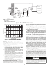
To determine that a TXV has failed, verify the following:
• The suction pressure is low and the valve is non-responsive.
The TXV sensing bulb can be removed from the suction
line and warmed by holding the bulb in your hand. This
action should result in an increase in the suction pressure
while the compressor is operating. The sensing bulb can
also be chilled by immersion in ice water, which should
result in a decrease in the suction pressure while the
compressor is operating. No change in the suction pres-
sure would indicate a nonresponsive valve.
• Simultaneous LOW suction pressure, HIGH refrigerant
subcooling and HIGH superheat may indicate a failed
valve.
• LOW suction pressure, LOW subcooling and HIGH super-
heat may indicate an undercharge of refrigerant. HIGH sub-
cooling and LOW superheat may indicate an overcharge of
refrigerant. The suction pressure will usually be normal or
high if there is an overcharge of refrigerant.
• LOW suction pressure and frosting of the valve and/or
equalizer line may indicate a failed valve. However, these
symptoms may also indicate an undercharge of refrigerant.
Calculate the subcooling and superheat to verify a failed
valve or refrigerant charge issue.
Repair
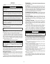
WARNING
Puron
®
refrigerant (R-410A) operates at higher pressure
than R-22, which is found in other WSHPs. Tools such as
manifold gages must be rated to withstand the higher pres-
sures. Failure to use approved tools may result in a failure
of tools, which can lead to severe damage to the unit, injury
or death.
WARNING
Most TXVs are designed for a fixed superheat setting and
are therefore considered non-adjustable. Removal of the
bottom cap will not provide access for adjustment and can
lead to damage to the valve or equipment, unintended vent-
ing of refrigerant, personal injury, or possibly death.
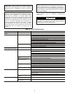
CAUTION
Use caution when tightening the strap. The strap must be
tight enough to hold the bulb securely but caution must be
taken not to over-tighten the strap, which could dent, bend,
collapse or otherwise damage the bulb.
CAUTION
Puron refrigerant (R-410A) requires the use of synthetic
lubricant (POE oil). Do not use common tools on systems
that contain R-22 refrigerants or mineral oil. Contamina-
tion and failure of this equipment may result.


