32
PRE-START-UP
System Checkout —
When the installation is complete,
follow the system checkout procedure outlined below before
starting up the system. Be sure:
1. Voltage is within the utilization range specifications of the
unit compressor and fan motor and voltage is balanced
for 3-phase units.
2. Fuses, breakers and wire are correct size.
3. Low voltage wiring is complete.
4. Piping and system flushing is complete.
5. Air is purged from closed loop system.
6. System is balanced as required. Monitor if necessary.
7. Isolation valves are open.
8. Water control valves or loop pumps are wired.
9. Condensate line is open and correctly pitched.
10. Transformer switched to lower voltage tap if necessary.
11. Blower rotates freely — shipping support is removed.
12. Blower speed is on correct setting.
13. Air filter is clean and in position.
14. Service/access panels are in place.
15. Return-air temperature is between 40 to 80 F heating and
50 to 110 F cooling.
16. Air coil is clean.
17. Control field-selected settings are correct.
AIR COIL — To obtain maximum performance, clean the air
coil before starting the unit. A 10% solution of dishwasher
detergent and water is recommended for both sides of the coil.
Rinse thoroughly with water.
FIELD SELECTABLE INPUTS
Jumpers and DIP (dual in-line package) switches on the
control board are used to customize unit operation and can be
configured in the field.
Complete C Control Jumper Settings
WATER COIL FREEZE PROTECTION (FP1) LIMIT
SETTING — Select jumper 3 (JW3-FP1 Low Temp) to
choose FP1 limit of either 30 F or 10 F. To select 30 F as the
limit, DO NOT clip the jumper. To select 10 F as the limit, clip
the jumper.
AIR COIL FREEZE PROTECTION (FP2) LIMIT SET-
TING — Select jumper 2 (JW2-FP2 Low Temp) to choose
FP2 limit of either 30 F or 10 F. To select 30 F as the limit, DO
NOT clip the jumper. To select 10 F as the limit, clip the
jumper.
ALARM RELAY SETTING — Select jumper 1 (JW1-AL2
Dry) to either connect alarm relay terminal (AL2) to 24 vac (R)
or to remain as a dry contact (no connection). To connect AL2
to R, DO NOT clip the jumper. To set as dry contact, clip the
jumper.
Deluxe D Control Jumper Settings
WATER COIL FREEZE PROTECTION (FP1) LIMIT
SETTING — Select jumper 3 (JW3-FP1 Low Temp) to
choose FP1 limit of either 30 F or 10 F. To select 30 F as the
limit, DO NOT clip the jumper. To select 10 F as the limit, clip
the jumper.
AIR COIL FREEZE PROTECTION (FP2) LIMIT SET-
TING — Select jumper 2 (JW2-FP2 Low Temp) to choose
FP2 limit of either 30 F or 10 F. To select 30 F as the limit, DO
NOT clip the jumper. To select 10 F as the limit, clip the
jumper.
ALARM RELAY SETTING — Select jumper 4 (JW4-AL2
Dry) to either connect alarm relay terminal (AL2) to 24 vac (R)
or to remain as a dry contact (no connection). To connect AL2
to R, DO NOT clip the jumper. To set as dry contact, clip the
jumper.
LOW PRESSURE SETTING — The Deluxe D control can
be configured for Low Pressure Setting (LP). Select jumper 1
(JW1-LP Norm Open) for choosing between low pressure
input normally opened or closed. To configure for normally
closed operation, DO NOT clip the jumper. To configure for
normally open operation, clip the jumper.
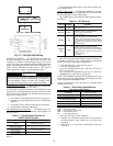
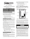
Complete C Control DIP Switches — The Com-
plete C control has 1 DIP (dual in-line package) switch bank
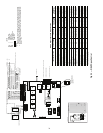
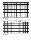
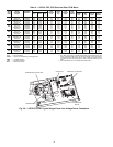
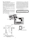
with five switches labeled SW1. See Fig. 15, 17, 18, 20, 21, or
23.
PERFORMANCE MONITOR (PM) — The PM is a unique
feature that monitors water temperature and will display a warn-
ing when heat pump is beyond typical operating range. Refer to
Control Operation section for detailed information. DIP switch
1 will enable or disable this feature. To enable the PM, set the
switch to ON. To disable the PM, set the switch to OFF.
STAGE 2 — DIP switch 2 will enable or disable compressor
delay. Set DIP switch to OFF for stage 2 in which the compres-
sor will have a 3-second delay before energizing.
NOTE: The alarm relay will not cycle during Test mode if
switch is set to OFF, stage 2.
SWITCH 3 — Not used.
DDC OUTPUT AT EH2 — Switch 4 provides a selection for
Direct Digital Control (DDC) operation. If set to DDC output
at EH2, the EH2 terminal will continuously output the last fault
code of the controller. If the control is set to EH2 Normal, then
EH2 will operate as standard electric heat output. Set the
switch to ON to set the EH2 to normal. Set the switch to OFF
to set the DDC output at EH2.
FACTORY SETTING — Switch 5 is set to ON. Do not
change the switch to OFF unless instructed to do so by the
factory.
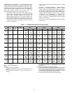
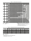
Deluxe D Control DIP Switches — The Deluxe D
control has 2 DIP (dual in-line package) switch banks. Each
bank has 8 switches and is labeled either S1 or S2 on the cir-
cuit board. See Fig. 16, 19, 22, or 24.
DIP SWITCH BANK 1 (S1) — This set of switches offers
the following options for Deluxe D control configuration:
Performance Monitor (PM)
— The PM is a unique feature
that monitors water temperature and will display a warning
when heat pump is beyond typical operating range. Set switch 1
to enable or disable performance monitor. To enable the PM, set
the switch to ON. To disable the PM, set the switch to OFF.
Compressor Relay Staging Operation
— Switch 2 will en-
able or disable compressor relay staging operation. The com-
pressor relay can be set to turn on with stage 1 or stage 2 call
from the thermostat. This setting is used with dual stage units
(units with 2 compressors and 2 Deluxe D controls) or in mas-
ter/slave applications. In master/slave applications, each com-
pressor and fan will stage according to its switch 2 setting. If
switch is set to stage 2, the compressor will have a 3-second
delay before energizing during stage 2 demand.
NOTE: If DIP switch is set for stage 2, the alarm relay will not
cycle during Test mode.
IMPORTANT: Jumpers and DIP switches should only
be clipped when power to control board has been turned
off.


