


3
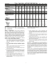
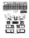
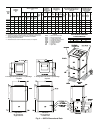
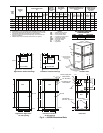
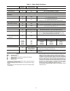
Table 1 — Physical Data — 50PSH, PSV, PSD018-070 Units
LEGEND *Unit sizes 006-012 not available on 50PSD unit.
NOTE: All units have spring compressor mountings, TXV expansion devices, and
1
/
2
-
in. and
3
/
4
-in. electrical knockouts.
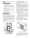
Step 2 — Check Unit — Upon receipt of shipment at
the jobsite, carefully check the shipment against the bill of
lading. Make sure all units have been received. Inspect the car-
ton or crating of each unit, and inspect each unit for damage.
Ensure the shipping company makes proper notation of any
shortages or damage on all copies of the freight bill. Concealed
damage not discovered during unloading must be reported to
the shipping company within 15 days of receipt of shipment.
NOTE: It is the responsibility of the purchaser to file all
necessary claims with the shipping company.
1. Be sure that the location chosen for unit installation pro-
vides ambient temperatures maintained above freezing.
Well water applications are especially susceptible to
freezing.
2. Be sure the installation location is isolated from sleeping
areas, private offices and other acoustically sensitive
spaces.
NOTE: A sound control accessory package may be used
to help eliminate sound in sensitive spaces.
3. Check local codes to be sure a secondary drain pan is not
required under the unit.
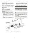
4. Be sure unit is mounted at a height sufficient to provide
an adequate slope of the condensate lines. If an appropri-
ate slope cannot be achieved, a field-supplied condensate
pump may be required.
5. Provide sufficient space for duct connection. Do not al-
low the weight of the ductwork to rest on the unit.
6. Provide adequate clearance for filter replacement and
drain pan cleaning. Do not allow piping, conduit, etc. to
block filter access.
7. Provide sufficient access to allow maintenance and
servicing of the fan and fan motor, compressor and coils.
Removal of the entire unit from the closet should not be
necessary.
8. Provide an unobstructed path to the unit within the closet
or mechanical room. Space should be sufficient to allow
removal of unit if necessary.
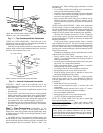
9. Provide ready access to water valves and fittings, and
screwdriver access to unit side panels, discharge collar,
and all electrical connections.
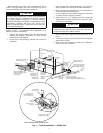
10. Where access to side panels is limited, pre-removal of the
control box side mounting screws may be necessary for
future servicing.
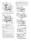
STORAGE — If the equipment is not needed immediately at
the jobsite, it should be left in its shipping carton and stored in a
clean, dry area of the building or in a warehouse. Units must be
stored in an upright position at all times. If carton stacking is
necessary, stack units a maximum of 3 high. Do not remove
any equipment from its shipping package until it is needed for
installation.
PROTECTION — Once the units are properly positioned on
the jobsite, cover them with either a shipping carton, vinyl film,
or an equivalent protective covering. Cap open ends of pipes
stored on the jobsite. This precaution is especially important in
areas where painting, plastering, or spraying of fireproof mate-
rial, etc. is not yet complete. Foreign material that accumulates
within the units can prevent proper start-up and necessitate
costly clean-up operations.
50PS UNIT SIZE 006* 009* 012* 018 024 030 036 042 048 060 070
COMPRESSOR (1 Each) Rotary Scroll
FACTORY CHARGE R-410A (oz) 24 32 34 50 56 58 70 80 80 136 144
ECM FAN MOTOR AND BLOWER
Fan Motor (Hp) N/A N/A N/A
1
/
2
1
/
2
1
/
2
1
/
2
1
/
2
111
Blower Wheel Size (D x W) (in.) N/A N/A N/A 9 x 7 9 x 7 9 x 7 11 x 10 11 x 10 11 x 10 11 x 10 11 x 10
PSC FAN MOTOR AND BLOWER
(3 Speeds)
Fan Motor (Hp)
1
/
25
1
/
20
1
/
8
1
/
6
1
/
5
1
/
3
1
/
2
1
/
2
3
/
4
11
High Static Fan Motor (Hp) N/A N/A N/A
1
/
5
1
/
3
1
/
2
1
/
2
3
/
4
3
/
4
1N/A
Blower Wheel Size (D x W) (in.) 6 x 5 6 x 5 6 x 5 9 x 7 9 x 7 9 x 7 10 x 10 10 x 10 10 x 10 11 x 10 11 x 10
Heat Exchanger Water Volume (gal.) 0.56 0.56 0.56 0.56 0.76 0.76 0.92 1.24 1.24 1.56 1.56
COAXIAL VOLUME (gal.) .17 .29 .45 .56 .76 .76 .92 1.24 1.24 1.56 1.56
WATER CONNECTION SIZE, FPT (in.)
1
/
2
1
/
2
1
/
2
3
/
4
3
/
4
3
/
4
3
/
4
1111
HWG CONNECTION SIZE, FPT (in.) N/A N/A N/A
1
/
2
1
/
2
1
/
2
1
/
2
1
/
2
1
/
2
1
/
2
1
/
2
VERTICAL UPFLOW/DOWNFLOW
Air Coil Dimensions (H x W) (in.) 16 x 16 16 x 16 16 x 16 24 x 20 28 x 20 28 x 20 28 x 25 32 x 25 32 x 25 36 x 25 36 x 25
Throwaway Filter, Standard 1-in.,
Qty...Size 1...
16 x 20
1...
16 x 20
1...
16 x 20
1...
24 x 24
1...
28 x 24
1...
28 x 24
1...
28 x 30
2...
16 x 30
2...
16 x 30
1...
16 x 30;
1...
20 x 30
1...
16 x 30;
1..
20 x 30
Weight
Operating (lb) 126 146 150 252 266 268 327 414 416 441 443
Packaged (lb) 136 156 160 262 276 278 337 424 426 451 453
HORIZONTAL
Air Coil Dimensions (H x W) (in.) 16 x 16 16 x 16 16 x 16 18 x 27 18 x 31 18 x 31 20 x 35 20 x 40 20 x 40 20 x 45 20 x 45
Throwaway Filter, Standard 1-in.,
Qty...Size 1...
16 x 20
1...
16 x 20
1...
16 x 20
2...
18 x 18
2...
18 x 18
2...
18 x 18
1...
12 x 20;
1...
20 x 25
1...
18 x 20;
1...
20 x 24
1...
18 x 20;
1...
20 x 24
2...
20 x 24
2...
20 x 24
Weight
Operating (lb) 136 156 160 257 266 268 327 414 416 441 443
Packaged (lb) 146 166 170 267 276 278 337 424 426 451 453
Corner (lb)
Left Front 45.0 55.0 56.0 74.7 78.8 79.4 104.4 144.3 145.0 182.3 183.1
Left Rear 33.0 36.0 37.0 66.2 69.9 70.4 83.7 97.7 98.1 78.4 78.8
Right Front 30.0 33.0 34.0 63.6 67.2 67.7 74.9 92.1 92.6 72.5 72.8
Right Rear 28.0 32.0 33.0 47.5 50.2 50.5 64.0 79.9 80.3 107.8 108.3
ECM — Electronically Controlled Motor PSC — Permanent Split Capacitor
FPT — Female Pipe Thread TXV — Thermostatic Expansion Valve
HWG — Hot Water Generator