


1
62--10458--00
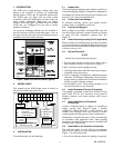
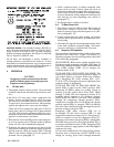
1. INTRODUCTION
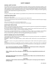
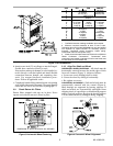
The 90M series single--package cooling units (See
Figure 1) are designed to provide air conditioning
aboard marine vessels and in industrial applications.
The 90MA units are fitted with sea water cooled
condensers while the 90MF units are fitted with fresh
water cooled condensers. Both units are factory
charged, wired and piped. The 90MU units are similar
except they are configured for use with a remote
mounted condenser.
An accessory dischar ge plenum may be i nstalled to
provide free--blow into the conditioned space. Also, an
accessory electric, hot water or steam coil heater may be
installed to provide comfort heating.
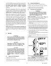
(90MA/MF
ONLY)
Figure 1 Base Unit Interior Details (Typical)
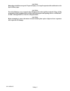
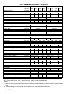
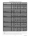
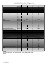
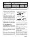
2. MODEL CHART
This manual covers 90M design series two units as
shown in the following model chart.
1 234567891011
9
0MA
3 1 2 --- 6 2
1
PRODUCT
CODE
MA - 90/10 Copper Nickel
Condenser
MF - Copper Condenser
MU - Condenserless
2-R-22
3 - R-134a
4 - R-407C
NOMINAL COOLING
CAPACITY (R--22)
VOLTAGE
5 - 208/230-3-60
6 - 460-3-60
9 - 400-3-50
PACKAGING
DESIGN
SERIES
MODEL
3. INSTALLATION
To install the unit, do the following:
3.1 Inspect Unit
Check unit against shipping order. Inspect carefully for
concealed shipping damage. If shipment is damaged or
incomplete,file claimwith transportation companyand
advise Carrier Transicold immediately.
3.2 Protect Unit from Damage
To maintain warranty, protect unit against adverse
weather, theft, or vandalism on j ob site.
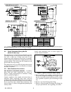
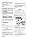
3.3 Provide Unit Support
Refer to Figure 2 and Table 1 through Table 2 for unit
size and weight. If desired, construct aframe ofI--beams
or angle iron that adequately supports unit. See
Figure 12.
3.4 Install Accessory Heating Coil (if applicable)
Electric heaters are installed at thetop of the unit. Water
or steam coil must be installed through the back of the
unit as described in the Installation Instructions shipped
with the accessory coil.
3.5 Rig and Place Unit
NOTE
Install accessories before placing unit.
a. Provide space around unit for service, filter access,
and overhead clearance as indicated in Figure 2.
b. Move and store unit in upright position.
c. Useslings with spacer under base skid to preventpan-
el damage when using hoist.
d. Units as shipped are adequately dampened against
vibration. If additional dampening is desired, place
sponge rubber or rubber mat, between deck and base
of unit or install vibration isolators.
e. Unit should be level. Unit leveling tolerance is 1/8
inch per linear foot in any direction.
3.6 Install Accessory Plenum (If Supplied)
Use plenum as template to mark hole locations in top
panel. Drill 5/32--in. (0.4 cm) holes in top panel at
marked locations and attach plenum with screws
supplied.
3.7 Install Ventilation--Air Ductwork
(If required)
Connect ventilation ducts to flanges on outside--air
supply opening (See Figure 2) using a flexible
connection. Attach ductwork to ship structure and
insulate with fiberglass and vapor barrier to reduce
sound transmission and prevent vapor condensation.
Weatherproof external ductwork, joints, and openings
in accordance with applicable codes. Ducts passing
through an unconditioned space must be insulated and
covered with a vapor barrier.
3.8 Install Return Air Ductwork (If required)
The unit back panel is to be field cut for alternate
return--air (or outdoor--air inlet) opening as indicated in
Figure 2. To install ductwork:
a. Cut out the alternate return -- air opening as required.