


12
62--10458--00
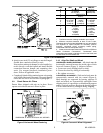
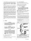
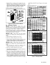
5.10 Evaporator Fan Motor Removal
a. Shut off unit main power supply.
WARNING
Lock open and tag unit disconnect before
working on f an motor. Remove fuses a nd
take them with you after noting this on tag.
CAUTION
Before attempting to r emove fan motors or
motor mounts, place a pieceof plywood over
evaporator coils to prevent coil damage.
b. Loosen motor hold down bolts on mounting bracket
so that fan belt can be removed. Motor power wires
need not be disconnected from motor terminals be-
fore motor is removed from unit.
c. Loosen but do not remove the 2 motor mounting
bracket bolts on left side of bracket.
d. Slide motor/bracket assembly to extreme right, re-
move bolts and lift out through space between fan
scroll and side. Rest motor on a high platform such as
astep ladder. Do not allow motor to hang by its power
wires.
5.1 1 Pressure Relief Device
All units are equipped with a fusible--plug type safety
relief device on the refrigerant tubing. The relief setting
is 197 _F to 203 _F on all units.
5.12 Crankcase Heater
A crankcase heater is supplied on the 008 & 012 size
units and on all 134a units. The heater prevents liquid
refrigerant from accumulating in the compressor
crankcase during extended shutdown periods. Heater is
automatically energized whenever unit main power is
on and compressor is stopped. Heater is de--energized
when compressor starts.
Do not shut off main power supply for an extended
period except for servicing unit. Turn on power supply
for at least 24 hours after an extended shutdown before
starting compressor. R efer to “Operation”.
5.13 Cycle--Loc
TM
-- Protection Device
All units are equipped with Cycle--LOC
current--sensing lockout relay. This device will lock out
the compressor after any safety trip (dischar ge pressure
switch, suction--pressure switch, or internal overload of
the compressor). Check reason for lockout before
resetting the device. Refer to unit label wiring diagram.
To reset, turn the system switch to OFF, then back to
COOL.
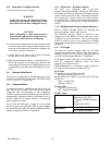
5.14
Discharge and Suction Pressure Switches
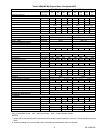
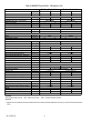
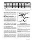
Refer to Table 1 through Table 2 for opening and
closing settings for these safety devices.
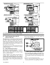
The discharge pressure switch is located on the
compressor on the 008 & 012 size units and on the
discharge line on all other units. The suction pressure
switch is located on top of the compressor on 06DR
compressor equipped units and on the suctionline onall
other units.
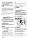
5.15 Oil Charge
All units are factory charged with oil. On 06D
compressors, observe the oil level in the sight glass at
start--up. If unit oil level is below sight glass, add oil
until level reaches approximately 1/4 sight glass.
If oil charge is above sight glass, do not remove any oil
until the compressor crankcase heater has been
energized for at least 24 hours.
When additional oil or a complete charge is required,
use only the following Carrier approved oil.
R-- 22 Units
Design Series One 204/206 size units
Witco part number 999--5170--55
Design Series One 208/212 size units and all Design
Series Two
Witco -- Suniso 3GS
Calumet -- RO--15
R--134a Units
Castrol -- Icematic E68
ICI -- Emkarate RL68HP
R--407C Units
004 and 006
Copeland Ultra 22CC
Mobil Artic EAL 22CC
ICI (Virginia KMP) Emkarate
RL32C
Thermal Zone 22CC
0
0
8
a
n
d
0
1
2
Castrol -- Icematic E68
008 and 012
ICI -- Emkarate RL68HP