


10
62--10458--00
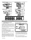
BELT TENSION ADJUSTMENT -- Shut off unit power
supply. Loosen fan motor from mounting bracket. Do
not loosen motormounting bracket from unit. Movefan
motor up or down until proper belt t ension is achieved
(approximately 3/4--in. deflection with 8--pound
tension at midpoint of belt span).
Lubrication -- Fan motor and fan shaft bearings are
lubricated for the life of the bearings. No re--lubrication
is required
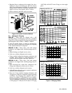
5.4 Return--Air Filter
Inspect filters twice monthly and clean as required by
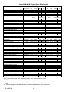
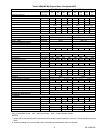
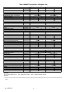
operating conditions. Filter size and type are listed i n
Table 1, Table 3 or Table 2. To clean filters flush with
hot water or steam or soak in a mild water solution of
soap or detergent. Refer to filter manufacturer’s
instructions as applicable. Do not operate unit without
return--air filters in place.
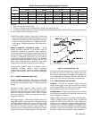
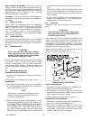
5.5 Condensate Drain
Clean the drain line and unit drain pan at the start ofeach
coolingseason. Check flowby pouringwater intodrain.
Be sure trap is filled as shownin Figure 7to maintainan
air seal.
5.6 Evaporator Coil
WARNING
Never reach into unit while fan is running.
Lock open and tag unit disconnect before
working on fan. Remove fuses and take them
with you after noting this on tag.
Remove dirt and debris from evaporatorcoil as required
by condition. Clean coil with a stiff brush, vacuum
cleaner or compressed air. Use a fin comb of the correct
tooth spacing (Refer to
Table 1, Table 3 or Table 2 for
coil fins/inch) when straightening mashed or bent coil
fins.
5.7 W ater Regulating Valve
PREPARATION FOR OPERATION.
a. Openthe water regulating valve inlet and outletisola-
tion valves.
b. Close the water regulating valve bypass valve.
ADJUSTMENT
a.
The compressor discharge pressure is controlled by
the water regulating valve and may be monitored by
observing liquid line pressure.
NOTE
Adjustments to the water regulating valve must
be made slowly, allowing ample time for re-
sponse and stabilization.
b. Install a calibrated gauge at the liquid line service
port. Operatingliquid line rangefor R--22 units is 250
to 270 psig (1724 to 1862 kPa), for R--134a units is
155 to180 psig (1069 to 1241 kPa) andfor R-- 407C is
267 to 288 psig (1841 to 1986 kPa). If pressure read-
ing is below operating range, rotate t he square head
adjusting screw counterclockwise; this will increase
spring tension, decrease water flow and increasepres-
sure.
If pressure reading is above operating range, rotate
the square head adjusting screw clockwise; this will
decrease spring tension, increase water flow and de-
crease pressure.
c. Only the water regulating valve opening point is ad-
justable. The closing point is 3 to 7 psig below the
opening point and is non--adjustable.
5.8 Condenser
Condensers may require cleaning of water--deposited
scale.
WARNING
Follow all Safety codes. Wear safety glasses
and rubber gloves when using inhibited hy-
drochloric acid solution.
Clean condensers with an inhibited hydrochloric acid
solution. The acid can stain hands and clothing, attack
concrete and, without inhibitor, can attack steel. Cover
surroundings to guard against splashing. Vapors from
vent pipe are not harmful, but take care to prevent liquid
from being carried over by the gases.
Warm solution acts faster, but cold solution is just as
effective if applied for a longer period.
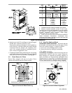
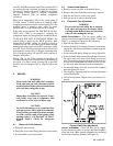
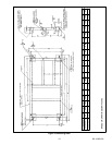
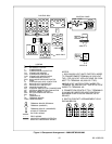
Figure 9 Gravity Flow Method
GRAVITY FLOW METHOD
a. Disconnect condenser piping at unit, including isola-
tion valves and water regulating valve.
b. Fill condenser as shown in Figure 9. Follow acid
manufacturer’s instructions. When condenser is full,
allow solution to remain overnight
c. Drain condenser and flush with clean water.
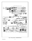
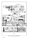
FORCED CIRCULATION METHOD
a. Disconnect condenser piping at unit, including isola-
tion valves and water regulating valve.
b. Fill system as shown in Figure 10. Follow acid
manufacturer’s instructions. Fully open vent pipe
when filling system. The vent may be closed when
system is full and pump is operating.