


8
62--10458--00
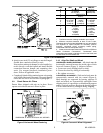
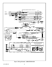
CONTROL WIRING -- On extended voltage (208/230--v)
units, thecontrol transformeris factory wired for 208--v
usage. If unit is to be used on 230--v system, reconnect
primary wiring on transformer. See Figure 13 (004/006
size) or Figure 15 (008/012 size).
On all units, the thermostat is factory installed. A
sensing element is provided in the return air. To wire
these units to a remote thermostat, or to a remotecontrol
switch and thermostat, refer to unit Wiring Diagram or
contact your Carrier Transicold representative.
4. OPERATION
CAUTION
Compr essor crankcase heater must be ener-
gized for24 hours prior to startup to prevent
compr essor bearing damage.
4.1 To Start Unit
a. Thoroughly inspect exterior of unit. Clean and dust
up debris, then wash with mild soap and water solu-
tion.
b. On 008 & 012 size units, ensure compressor dis-
charge, suction and liquid service valves are open.
The valves are accessible from the front of the unit.
To open valve, turn counterclockwise. Afteropening,
replace and tighten valve cap to prevent leakage.
Check oil level in compressor sight glass. If level is
below glass, add oil to bring level to approximately
1/4 glass. If level is above bottom of glass, do not re-
move any oil until the crankcase heater has been ener-
gized for at least twenty--four hours.
c. With selector switch in OFF position, turn mainpow-
er on. Leave power on for 24 hours so that crankcase
heater can drive off accumulated refrigerant.
d. If desired, the selector switch may be placed in the
FAN position during the crankcase warm -- up period.
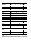
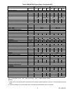
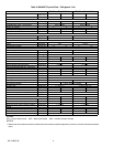
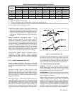
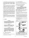
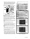
On first start--up, check fan speed (Table 1 through
Table 2) and rotation (Figure 1). If fan requires ad-
justment, refer to paragraph 5.3.
e. Allow c rankcase heater to remain energized (unit
power on) for at least 24 hours. Open any valves in
condenser cooling water supply lines and then set se-
lector switch at COOL position. If room temperature
is above thermostat setting compressor will start. On
first start--up, set water regulating valve. (Refer to
paragraph5.7.)
f. Set thermostat for comfort as desired.
4.2 To Shut Down Unit
a. Turn selector switch to OFF position. Do not shut off
main power except to service unit. The crankcase
heater is operative only when main power is on. (Re-
fer to paragraph 5.12).
b. If unit is t o be used for winter heating, set selector
switch at HEAT position and re--set thermostat at de-
sired setting.
c. Ifunit may beexposed tofreezing temperatures, drain
water from condenser and water piping. Add a non-
corrosive antifreeze to residual water in system.
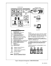
4.3 Sequence Of Operation
Unit operation is dependent on the position of the mode
selector switch. (See note 3, Figure 14
or Figure 16.)
Operation sequence for each switch position is provided
in the following paragraphs.
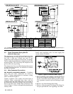
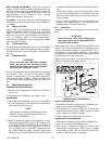
OFF POSITION: With correct voltage supplied at the
fieldpower supplyterminals, see
Figure 13or Figure 15
power flows through normally closed crankcase heater
relay (CHR) contacts (CHR, 4/5) to energize the
crankcase heater (CH).
TO PLACE THE UNIT IN THE FAN MODE: The
switch (SW) is placed in the FAN position to supply 24
volt control power, to energize indoor fan contactor
(IFC). Energizing IFC closes contacts (IFC, 11/21,
12/22 & 13/23) to energize the motor. Operation of the
crankcase heater is maintained.
TO PLACE THE UNIT IN THE COOL MODE: The
switch (SW) is placed in the COOL position. With
thermostat (T--LOW) calling for cooling (closed to
contacts R & W) control power flows from TRAN
through T--LOW, SW and compressor lockout (CL)
normally closed contacts to the discharge pressure
switch (DPS). On 008/012 size units, flow continues
through the compressor internal protector (IPC),
compressor overloads (OLA & OLB) and the suction
pressure switch (SPS), to energize CHR. On 004/006
size units, flow continues directly thorough the suction
pressure switch to energize CHR.
Energizing CHR opens contacts CHR 4--5 to
de--energize CH and closes contacts CHR 1--3 and
energizethe compressor contactor(CC). EnergizingCC
closes its contacts t o start the compressor motor (C).
Operation of the indoor fan motor (IFM) is maintained.
On 90MU units, power also flows from terminal TB1--5
to energize condenser fan relay (CFR). Energizing CFR
closes its contacts to supply power to the field supplied
condenser fan relay.
012 sizeunits arefitted witha two stage coolingsystem.
On these units, if thermostat switch T--HIGH is also
calling for cooling, power flows through thermostat