


7
62--10458--00
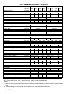
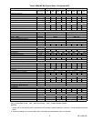
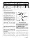
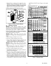
Table 4 Recommended Line Sizes, Remote Condenser
UNIT
LENGTH OF RUN
(90MU)
0-- 25 26--50 51--75 76--100
(
)
DISCH LIQUID DISCH LIQUID DISCH LIQUID DISCH LIQUID
004 1/2 (1.3) 1/2(1.3) 5/8(1.6) 1/2(1.3) 5/8(1.6) 1/2(1.3) 7/8(2.2) 1/2(1.3)
006 5/8(1.6) 1/2(1.3) 7/8(2.2) 1/2(1.3) 7/8(2.2) 1/2(1.3) 7/8(2.2) 1/2(1.3)
008 7/8(2.2) 5/8(1.6) 7/8(2.2) 5/8(1.6) 7/8(2.2) 5/8(1.6) 1-1/8(2.9) 5/8(1.6)
012 7/8(2.2) 5/8(1.6) 1-1/8(2.9) 5/8(1.6) 1-1/8(2.9) 5/8(1.6) 1-1/8(2.9) 5/8(1.6)
NOTES:
1. Line sizes given in inches (cm).
2. Line sizes should never be smaller than cooling unit connection size.
3. A nominal number of fittings has been considered in determining line sizes. Smaller line sizes may be considered
if run is simple and few fittings are used.
d. Hold flare tightly against fitting while connecting
flare nut. Round end of cotter pin will depress core of
fitting. The opened fitting allows refrigerant pressure
to act on water regulating valve. Tighten nut to pre-
vent leakage. Fitting automatically seals when nut is
removed.
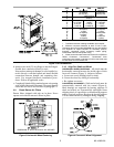
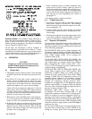
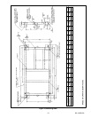
REMOTE MOUNTED CONDENSER (90MU) -- I n s t a l l
remote mounted condenser i n accordance wi th the
installation instructions provided with condenser.
Connection locations for liquid and discharge lines are
shown i n Figure 5. Recommended line sizes are given
in Table 4. Additional instructions can be found in
Carrier S ystem Design Manual, Part 3, for standard
refrigeration piping techniques. On 008 and 012 size
units, secure discharge line to bracket at unit outlet
using proper clamp from supplied fastener package
Condenserless (90MU) units are shipped with a
refrigerant holding charge. After refrigerant
connections are made, leak test, r eclaim refrigerant,
evacuate, and charge system as described in paragraph
5.9.
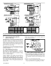
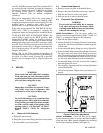
3.13 Install Condensate Drain Line
Install a trapped condensate drain line at unit drain
connection. The drain requires standard pipe connected
to condensate pan nipple(s). Figure 7 shows proper trap
design.
Determine design negative static pressure. This
pressure is not the same as fan total static pressure,
which includes pressure losses downstream as well as
upstream from the evaporator air fan. Always assume
the worst conditions, such as having return air filters
clogged with debris.
Referring to Figure 7, differential 1 must be equal to or
larger than negative static pressure at design operating
condition. Store enough water in trap to prevent losing
seal. Differential 2 must be equal to or larger than
one--half the maximum negative static pressure. To
avoid loss of seal when the fan starts, differential 3 must
be greater than the maximum negative static pressure.
Figure 7 Condensate Drain Trap
Do not use drain line smaller than 3/4 inch. Use hole(s)
provided in panel for drain line. Pitch drain line
downward t oward scupper. Installation of a plugged tee
is recommended for cleaning. Fill trap with water to
make an air seal. Observe all sanitary requirements.
3.14 Make Electrical Connections
GENERAL -- P rovide an adequate fused disconnect
switch within sight of the unit. Provision for locking
switch open (OFF) is advisable t o prevent power from
being t urned on when unit is being serviced.
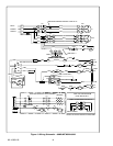
POWER WIRING -- Conduit opening for all units is on left
side of unit near control box. Connect field power wires
at the compressor contactor.
Supply voltage must be in accordance with nameplate
voltage. Voltage between phases must be balanced
within 2% and current within 10% with compressor
running. Correct improper voltage or phase imbalance.
Unit failure as a result of operation on improper line
voltage or excessive phase imbalance constitutes abuse
and shall void the Carrier warranty. Use the following
formula to determine the percent voltage imbalance.